RN2483 PICTail + Arduino Node

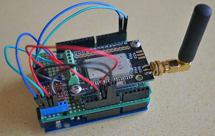
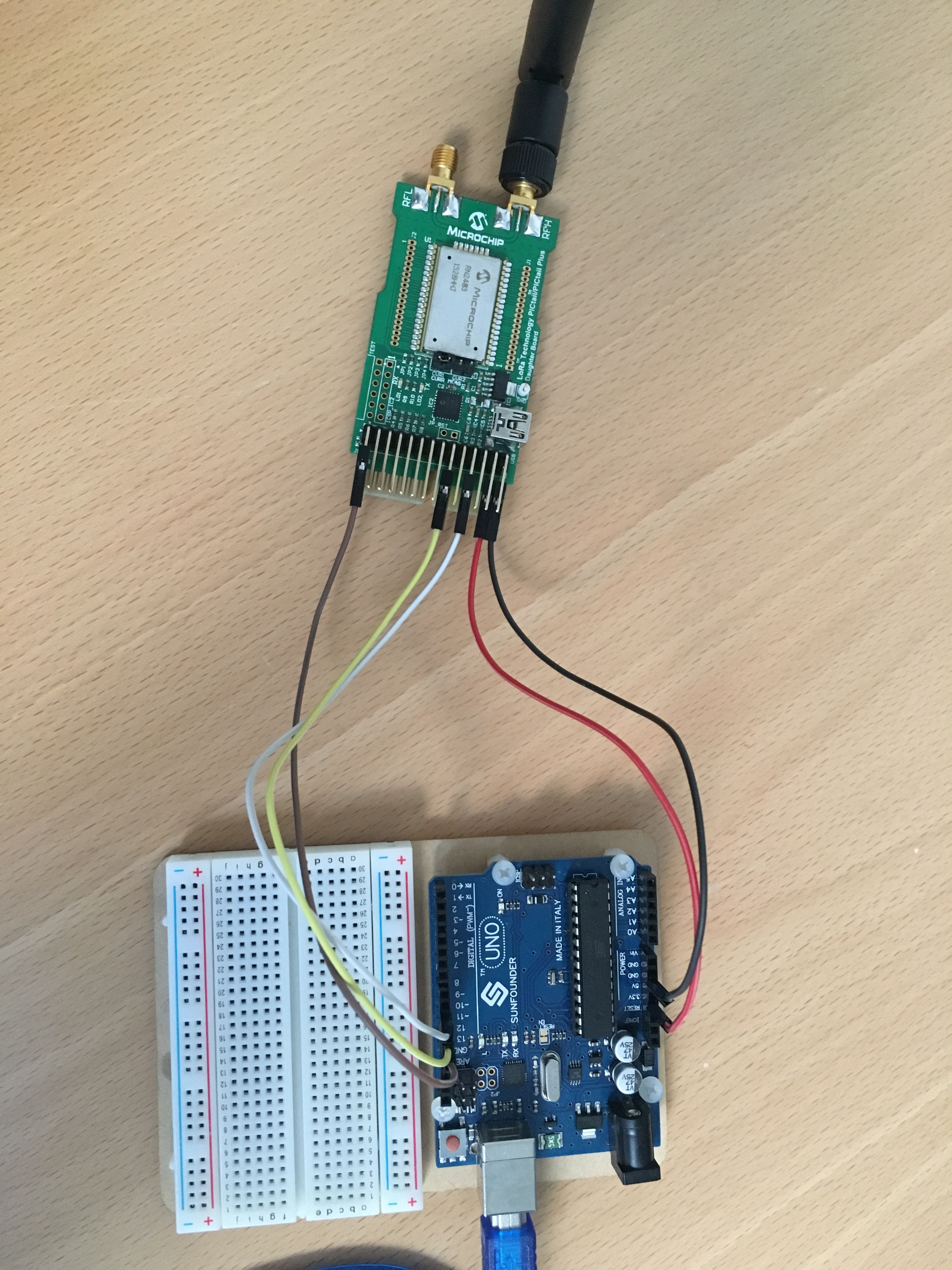
Hello, i am trying to make a LoRa node, with a RN2483 PICTail board, and an Arduino.
And the node should be powered by a battery, so i can have it ex. in my car.

I have used this post, to get the Arduino code, and the connections to the RN2483 chip.

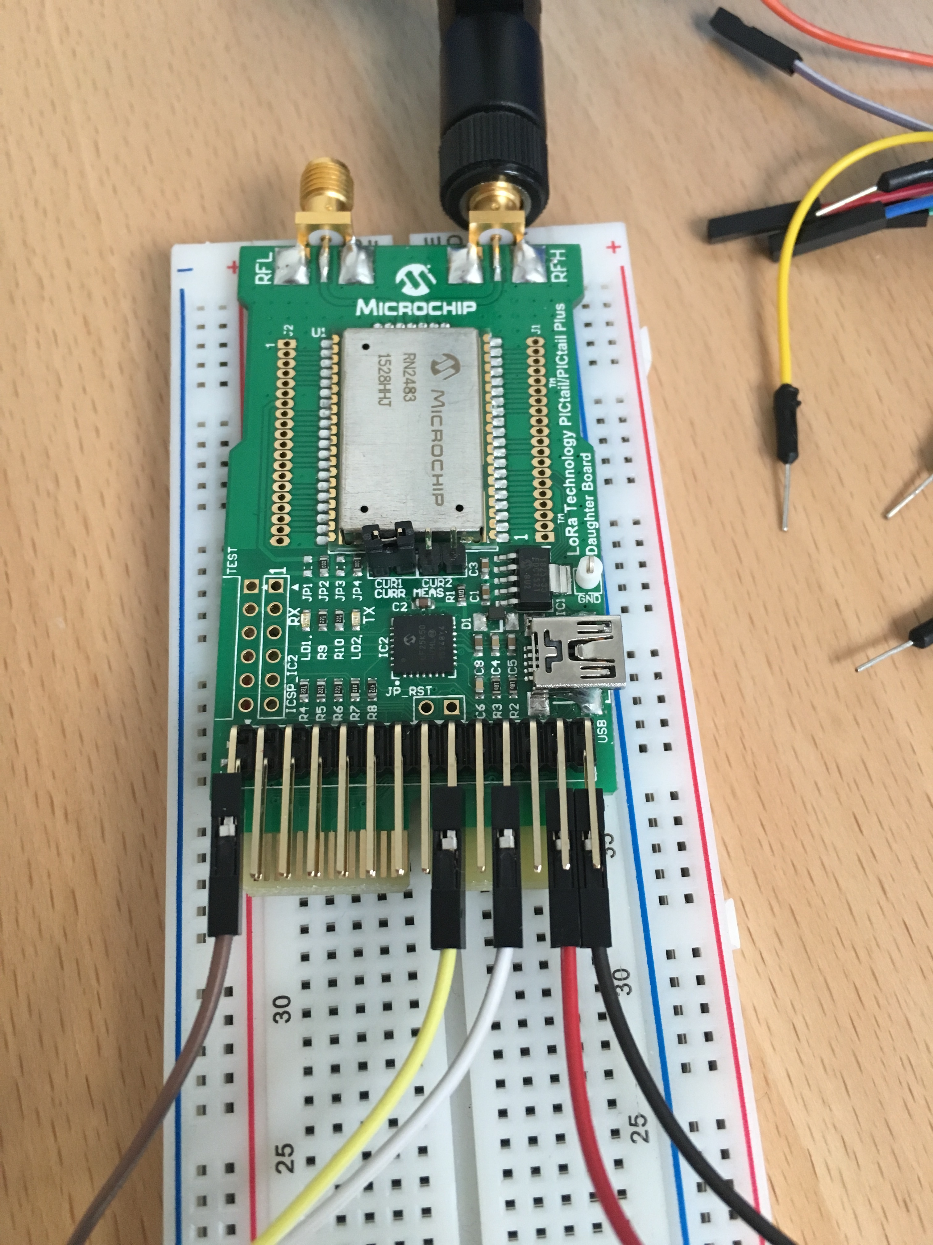
I then used the RN2483 PICTail userguide here, to find the pins on the board (page 20).

But i don’t seem to get it to send.

Do i need to power the RN2483 board with USB and 3.3V from the arduino at the same time ??
And is what i have done even possible, or do i wreck the boards ??

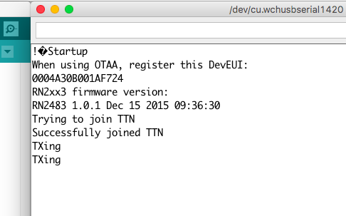
Yesterday i updated the RN2483 to ver. 1.0.1

I’ve tried both with an Arduino Uno and Nano, the code works and i get feedback to the serial monitor.

Thanks in advance :slight_smile:

-KasperS

the gnd’s should be connected, if you use it in your car, you will need a DC / DC regulator to bring down the car battery voltage from 12 to 3V3

I would not use the car battery, but a 5v power bank to the arduino’s usb.

I have connected the and from the RN2483 (pin 28) to god on the arduino, and the 3.3v (pin 26) to 3.3v on the arduino.

what type of arduino ? because the 3v3 output on the arduino is maybe not strong enough for your rn2483

  • in the article it’s an UNO I see now :innocent:

if you get feedback from the ide monitor it means that the connections Rx/Tx are good
you also have a new firmware version.

so what’s the problem now ?
possibly something in your code, keys maybe ?

yes, it’s an UNO, but i also tried an NANO.

i have been looking through the library that from the post i linked to, and it sends the same commands as when i just use a terminal on my mac and USB connection to the board.

My problem is that the board’s led’s do not light up at all when i connect it up like this:

but i can’t see why i shouldn’t be able to do it like this, in the user guide, it says that it can be powered by the usb or PIC connectors…

ok… so the board connected same way but to an usb serial works (ide terminal picture)

  • can you meassure if the rn2483 really is getting 3V3 ? (on the chip) like its connected now

i just tried to power the RN2483 board by USB (only 5v and GND) and the Arduino, but still nothing…

so i think it’s the code that is the problem :disappointed_relieved:

i will try to do some measurements on the board, to see if i get the voltage i need…

  • I do get 3.3v at the chip, with only the Arduino to power the RN2483, so i think there is some problems with the code…

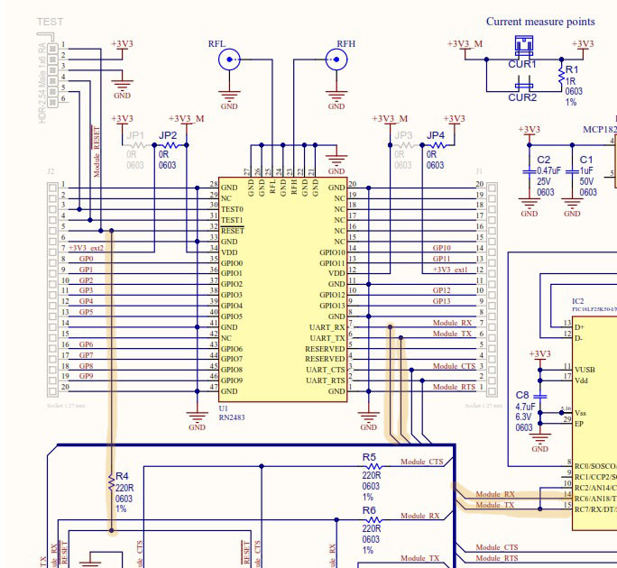
I don’t know that module, but if I look at the schematic, then I see that the RN2483 is stil connected, not only externly to your RxTx UNO but also to the usb serial… and that chip still gets power to, could that be a 'conflict ?
are there jumpers somewhere on the board to disconnect ? just an idea … :innocent:

I did not think about that… :open_mouth:, i will have to check that.

There is only two jumpers, and they are for current measuring (top right of your pic.)

I also have to check that my arduino is working, because i have a slight suspicion that my arduino is faulty.

Thanks for your inputs @BoRRoZ :slight_smile:

and don’t forget that the UART voltage level is 3v3 (use levelshifter) between UNO and RN2483

1 Like

Hello sir,
Did you get the results for RN2483 PIC tail+ARDUINO?

Hello,
Yes, i got the PICtail to work with the arduino.

you need a Logic Level Shifter to transform the 5V signals from the arduino down to 3.3V for the RN2483

I will try to write a post this weekend, explaining what i did to make it work :slight_smile:

Thank you so much.

guys i bought two RN2483 Pictail plus lora modules and i want to communicate P2P is it possible with this lora module? please help me in this, thankyou in advance