I’d like to connect a RFM95W to a Samd21 mini. Does anyone know which connections to make?
I tried connecting like an Arduino Pro Mini but I’m not sure this will work. Also, I am confused since the pins on the Samd21 mini board have no pin numbers but functional titles like GND, RST or D7 or A1. So what pin numbers should I refer to then in my sketch? How to solve this. Really would appreciate some help.
You may want to look up the connections on the Adafruit Feather LoRaWAN (plus required DIO modifiaction for LMiC) as that as a bit of a well supported reference platform, and then see if you can translate them to the way your board routes actual MCU pins to connectors.
Another way of approaching it is that your SPI pins need to be whatever your Arduino BSP puts the default SPI interface on (unless you modify the SPI code), and then your DIO and radio reset pins can be whatever you have available.
For a first effort, using exactly what your source software uses will make life simpler. Eg, the maintained Arduino LMiC option is from MCCI, and the feather board is one of the reference platforms they test on, so you are least likely to encounter novel issues when using that actual board.
Hi Jens,
Thx for your comment. Yes, I’m aware of ready-made products. I own an Arduino Zero with LoRa shield and an Adafruit Feather M0 with RFM95 built in. Both are working nodes in the TTN. I thought it would be fun to build a node myself with an other (cheap) board and RFM95. It is fun, but also a bit of a hassle This way I learn a lot of things. And others may also profit from my experiences.
Roel
These experiences are very valueable especially when they public avaibel.
Samd21 MCUs are used in many other DIY projects.
When the information and basic sketches are availabel it is probaly a low cost entry for someone with a usecase for LoraWan/TTN and having a generic mcu laying around. Or perhaps it is possibel to extend an existing SAMD21 based project with wiring infomation and sketches availabel.
Hi cslorabox,
Thanks for your tips.Unfortunately I did not succeed yet. Somehow it’s too complicated for me to translate the pinfunctions to the standard numbering of an Arduino Zero or Adafruit Feather.
Are you using the Arduino eco-system to program this home-made board?
If so, you probably want to look at duplicating a board support file for Arduino for something that matches closest and altering it. Or even just looking at how they work for something like the Feather so you can see how the real world physical pins of a MCU are mapped to the Arduino pin names.
Yes, I’m using the Arduino IDE. But before I step into programming and uploading my sketch I’d like to be sure about the pins I have to use in my code. And of course physical connections to the right pins.
There’s an implication here that you are hoping someone will have the answers which clearly hasn’t happened thus far.
But a quick look at the SparkFun website for details on this board and it looks like it’s “Just Another Arduino Board”, that is to say, it’s Arduino on screen so will work (mostly) with the libraries on offer and the pin numbers you see are, well Arduino style pin numbers so you can use the Arduino instructions for the MCCI LMIC library and, apart from the SPI pins, assign your own DIO0 & DIO1 to what ever pins float your boat and, if you want belt & braces, assign a RST.
The real giveaway is that Sparkfun say they’ve made it the same form-factor as their original Pro Mini along with multiple references to Arduino. So you could crack on assuming you have a souped up Pro Mini to connect.
The MCCI LMIC has plenty of documentation on connecting which pins where.
Or put all that another way, D4 is actually D4 which from most of the Arduinos I see is usually marked 4, so I 'd say you are way over thinking this
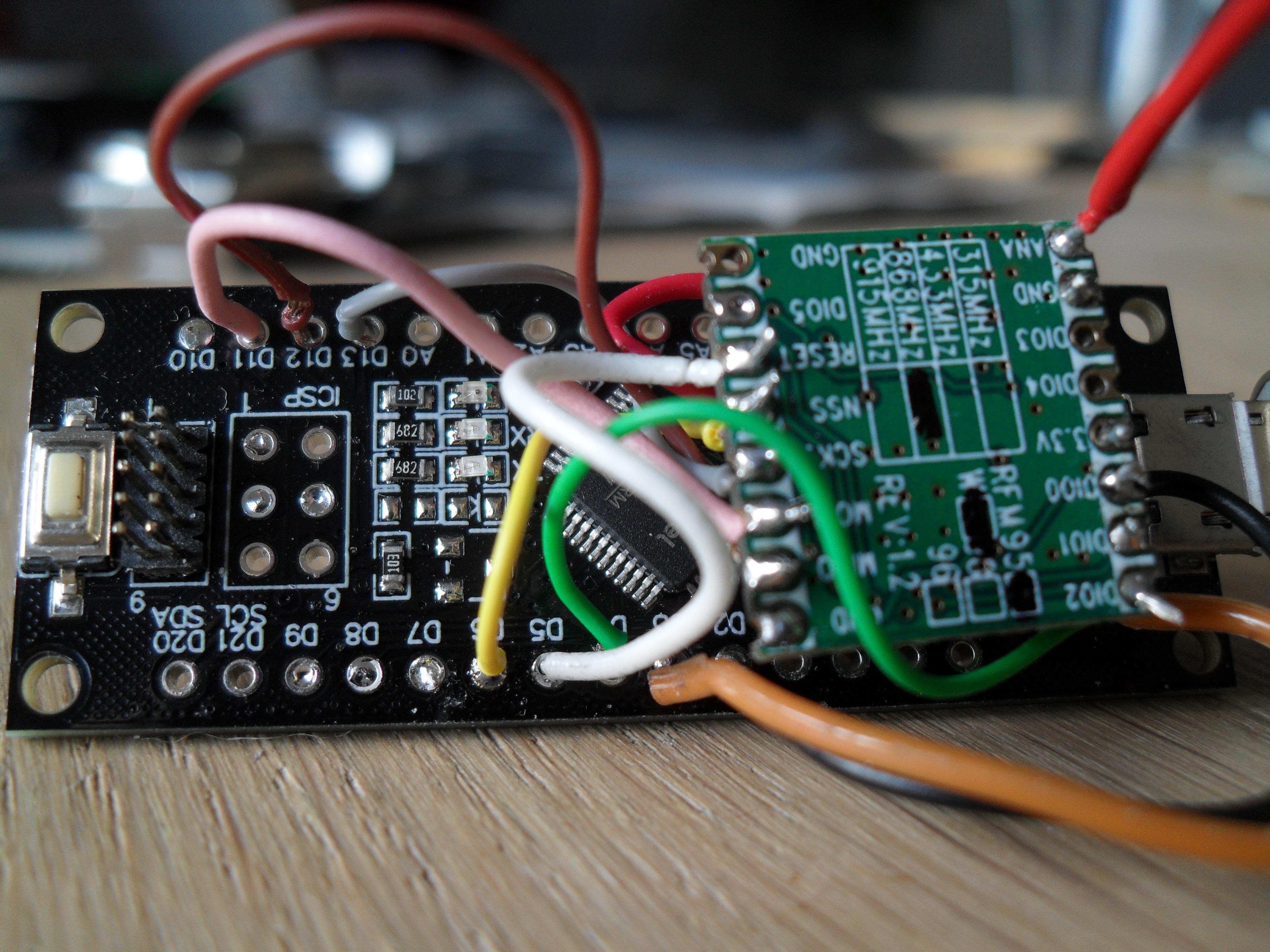
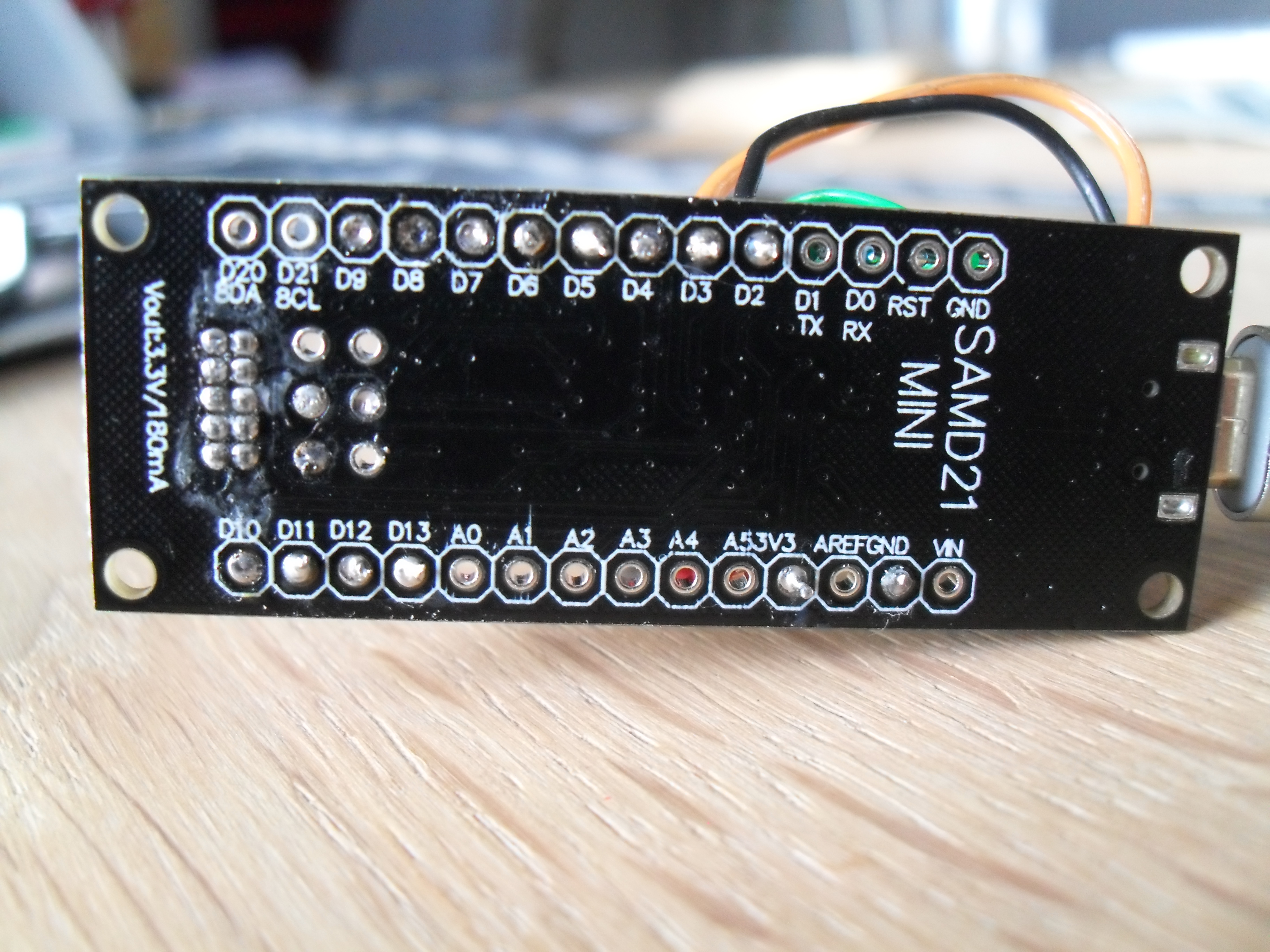
Made some progress, but board is not working yet. My board is not a genuine Arduino Pro Mini but a SAMD21 mini. I presume that this is a clone with the same form-factor and wired the RFM95W board to the SAMD21 like on this page.
I use this pin mapping:
const lmic_pinmap lmic_pins = {
.nss = 6, // chip select on SAMD21 mini
.rxtx = LMIC_UNUSED_PIN,
.rst = 5, // reset pin
.dio = {2, 3, 4}, // DI0, DI1, DI2
};
I updated my Arduino IDE: Arduino SAMD boards from v 1.8.8. to v 1.8.10; installed an Arduino USB driver (that just popped up during the update process) and updated the library MCCI Lorawan LMIC from v 3.2.0 to v 3.3.0
When I compile my code it says my board is not supported (I choose Arduino Zero (Native USB port), and I should use Explicit Pin mapping (which I do in the code). Uploading goes well, but the Serial Monitor does not appear when I request for it via the Tools menu. In the code I put // just before the
While Serial command, like this:
// while (!Serial); // wait for Serial to be initialized
So the program will not wait for this port to be ready. When I physically disconnect my board from the usb port it suddenly does appear, but with no output at all. So… I guess something is wrong in my IDE or code.
That’s no moon … … or at least not a SAMD21. It is an Arduino Pro Mini which you’ll find in the AVR section of the IDE for board selection.
I can’t tell if it’s a 3.3V 8MHz board, which would be preferable, or if it’s a 5V 16MHz, which runs the risk of overloading the RFM board. The way to tell is to do a Blinky sketch & choose the 3.3V option and then see how fast it blinks - if you are on a 8MHz board, it will run at normal speed. If it blinks slowly time, then it’s a 5V.
Perhaps it’s a SAMD21 board without an Arduino boot loader.
Do you have another one you can try? Or another Arduino so you can program it via the ICSP or get a boot loader on to it?
Either way, it’s unlikely to be a function of the LoRaWAN element if your IDE / programming isn’t even getting started.
Can you give us the actual detail on this - is this the LMIC saying it’s not supported or the IDE saying it’s not supporting the board?
Can you try one of the basic examples - like DigitalReadSerial. It is common for some boards to need a wait loop for the Serial port to be initialised so you should try with & without.
C:\Users\RoelV\Documents\Arduino\libraries\MCCI_LoRaWAN_LMIC_library\src\hal\getpinmap_thisboard.cpp: In function ‘const Arduino_LMIC::HalPinmap_t* Arduino_LMIC::GetPinmap_ThisBoard()’:
C:\Users\RoelV\Documents\Arduino\libraries\MCCI_LoRaWAN_LMIC_library\src\hal\getpinmap_thisboard.cpp:69:72: note: #pragma message: Board not supported – use an explicit pinmap #pragma message(“Board not supported – use an explicit pinmap”)
^
Sketch uses 31060 bytes (11%) of program storage space. Maximum is 262144 bytes.
Global variables use 3192 bytes (9%) of dynamic memory, leaving 29576 bytes for local variables. Maximum is 32768 bytes.
When i compile DigitalReadSerial the IDE says:
Sketch uses 11676 bytes (4%) of program storage space. Maximum is 262144 bytes.
Global variables use 2204 bytes (6%) of dynamic memory, leaving 30564 bytes for local variables.
When I compile and Upload DigitalReadSerial the IDE says:
Sketch uses 11676 bytes (4%) of program storage space. Maximum is 262144 bytes.
Global variables use 2204 bytes (6%) of dynamic memory, leaving 30564 bytes for local variables. Maximum is 32768 bytes.
Forcing reset using 1200bps open/close on port COM10
processing.app.debug.RunnerException
	at cc.arduino.packages.uploaders.SerialUploader.uploadUsingPreferences(SerialUploader.java:152)
	at cc.arduino.UploaderUtils.upload(UploaderUtils.java:77)
	at processing.app.SketchController.upload(SketchController.java:732)
	at processing.app.SketchController.exportApplet(SketchController.java:703)
	at processing.app.Editor$UploadHandler.run(Editor.java:2055)
	at java.lang.Thread.run(Thread.java:748)
Caused by: processing.app.SerialException: Error touching serial port 'COM10'.
	at processing.app.Serial.touchForCDCReset(Serial.java:107)
	at cc.arduino.packages.uploaders.SerialUploader.uploadUsingPreferences(SerialUploader.java:136)
	... 5 more
Caused by: jssc.SerialPortException: Port name - COM10; Method name - openPort(); Exception type - Port busy.
	at jssc.SerialPort.openPort(SerialPort.java:164)
	at processing.app.Serial.touchForCDCReset(Serial.java:101)
	... 6 more
PORTS {COM10, } / {} => {}
PORTS {} / {} => {}
PORTS {} / {COM4, } => {COM4, }
Found upload port: COM4
C:\Users\RoelV\AppData\Local\Arduino15\packages\arduino\tools\bossac\1.7.0-arduino3/bossac.exe -i -d --port=COM4 -U true -i -e -w -v C:\Users\RoelV\AppData\Local\Temp\arduino_build_546434/DigitalReadSerial.ino.bin -R
Set binary mode
readWord(addr=0)=0x20007ffc
readWord(addr=0xe000ed00)=0x410cc601
readWord(addr=0x41002018)=0x10010305
version()=v2.0 [Arduino:XYZ] Dec 20 2016 15:36:41
chipId=0x10010005
Connected at 921600 baud
readWord(addr=0)=0x20007ffc
readWord(addr=0xe000ed00)=0x410cc601
readWord(addr=0x41002018)=0x10010305
Atmel SMART device 0x10010005 found
write(addr=0x20004000,size=0x34)
writeWord(addr=0x20004030,value=0x10)
writeWord(addr=0x20004020,value=0x20008000)
Device       : ATSAMD21G18A
readWord(addr=0)=0x20007ffc
readWord(addr=0xe000ed00)=0x410cc601
readWord(addr=0x41002018)=0x10010305
Chip ID      : 10010005
version()=v2.0 [Arduino:XYZ] Dec 20 2016 15:36:41
Version      : v2.0 [Arduino:XYZ] Dec 20 2016 15:36:41
Address      : 8192
Pages        : 3968
Page Size    : 64 bytes
Total Size   : 248KB
Planes       : 1
Lock Regions : 16
Locked       : readWord(addr=0x41004020)=0xffff
readWord(addr=0x41004020)=0xffff
readWord(addr=0x41004020)=0xffff
readWord(addr=0x41004020)=0xffff
readWord(addr=0x41004020)=0xffff
readWord(addr=0x41004020)=0xffff
readWord(addr=0x41004020)=0xffff
readWord(addr=0x41004020)=0xffff
readWord(addr=0x41004020)=0xffff
readWord(addr=0x41004020)=0xffff
readWord(addr=0x41004020)=0xffff
readWord(addr=0x41004020)=0xffff
readWord(addr=0x41004020)=0xffff
readWord(addr=0x41004020)=0xffff
readWord(addr=0x41004020)=0xffff
readWord(addr=0x41004020)=0xffff
none
readWord(addr=0x41004018)=0
Security     : false
Boot Flash   : true
readWord(addr=0x40000834)=0x7000a
BOD          : true
readWord(addr=0x40000834)=0x7000a
BOR          : true
Arduino      : FAST_CHIP_ERASE
Arduino      : FAST_MULTI_PAGE_WRITE
Arduino      : CAN_CHECKSUM_MEMORY_BUFFER
Erase flash
chipErase(addr=0x2000)
done in 0.823 seconds

Write 11676 bytes to flash (183 pages)
write(addr=0x20005000,size=0x1000)
writeBuffer(scr_addr=0x20005000, dst_addr=0x2000, size=0x1000)
[==========                    ] 34% (64/183 pages)write(addr=0x20005000,size=0x1000)
writeBuffer(scr_addr=0x20005000, dst_addr=0x3000, size=0x1000)
[====================          ] 69% (128/183 pages)write(addr=0x20005000,size=0xdc0)
writeBuffer(scr_addr=0x20005000, dst_addr=0x4000, size=0xdc0)
[==============================] 100% (183/183 pages)
done in 0.087 seconds

Verify 11676 bytes of flash with checksum.
checksumBuffer(start_addr=0x2000, size=0x1000) = 6b83
checksumBuffer(start_addr=0x3000, size=0x1000) = 6d6b
checksumBuffer(start_addr=0x4000, size=0xd9c) = a6cf
Verify successful
done in 0.013 seconds
CPU reset.
readWord(addr=0)=0x20007ffc
readWord(addr=0xe000ed00)=0x410cc601
readWord(addr=0x41002018)=0x10010305
writeWord(addr=0xe000ed0c,value=0x5fa0004)
During the upload I have to reset the board twice fast, to make it recognize the port, or vice versa.
I have used this IDE before with an Arduino Uno and an Adafruit Feather M0. It worked, but with the same sort of COM port troubles. And I have to reset the Feather twice during upload to make the IDE find the board. Sometimes Serial Monitor works and sometimes not. Appreciate your help very much, but don’t let it consume all your time…
This just means you’ve not told it what board you are using or if you have, it doesn’t know that board so you have to set up the pins - which you have done.
I do macOS, Linux and Windows in that order, so I’m not best placed to comment on the serial ports. Some boards do need prompting before a download. My Adafruit Feather doesn’t need a reset and only shows one serial port. You may want to make enquiries on the Arduino forum / eco-system if no one chimes in here.
 This way I learn a lot of things. And others may also profit from my experiences.
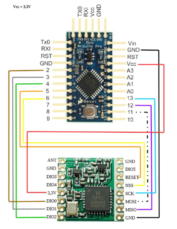
 It’s a 3.3V board, powered by usb.