Has anyone ever had a Seeeduino XIOA working on TTN ?
Just about enough pins, but wondered if you can diode OR DIO0, DIO1, DIO2 to a single IO pin on the XIOA ?
I did find this;
Where they appear to have DIO0 on one pin and DIO1,DIO2 on another.
Has anyone ever had a Seeeduino XIOA working on TTN ?
Just about enough pins, but wondered if you can diode OR DIO0, DIO1, DIO2 to a single IO pin on the XIOA ?
I did find this;
Where they appear to have DIO0 on one pin and DIO1,DIO2 on another.
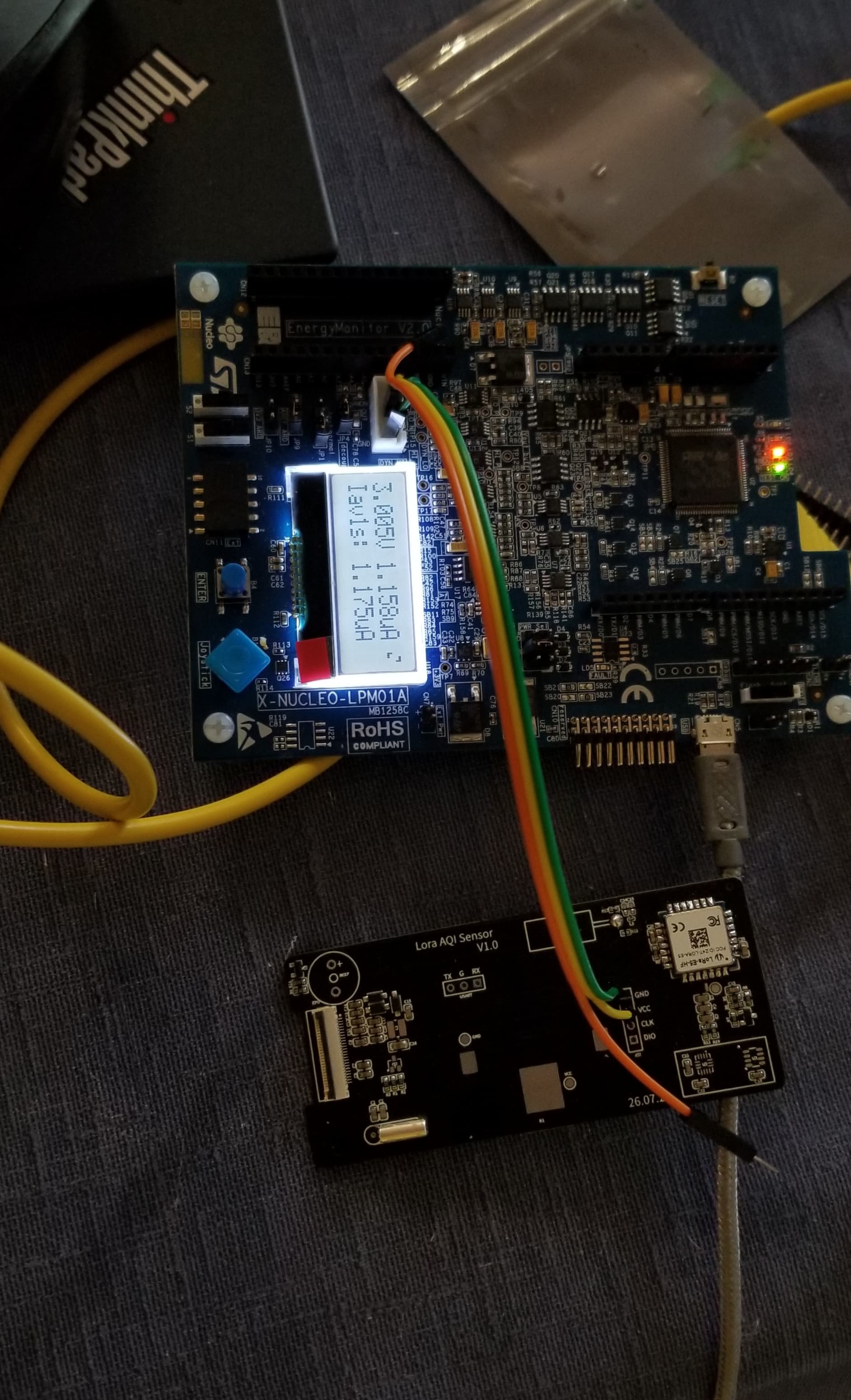
Just been testing.
I am getting a 6uA sleep current with an RFM95 and the real time clock alarm waking the device up.
And 19uA sleep current when set to wakeup from external hardware interupt.
You can try seed-E5 module, the stop2(with rtc&exti wakeup capability)current is around 1.2uA.
The Seed E5 is a very interesting module for sure, and I do have a couple on order. Maybe a bit small for easy DIY, but I guess 1mm pin headers would make that easy enough.
I raised the issue of connecting DIO0,DIO1,DIO2 to the same pin as a result of a little project I was working on;
I find it easy enough to solder up a PCB with small SMT stuff, but I know a lot of people are not so keen. Now a combination of the XIOA and an RFM95 would be very easy to put together, you can use 0.1" and 2mm pin headers respectivly.
So it occured to me that an XIOA\RFM95, would make a small, low cost, easy to put together TTN node. If you could just use one DIO pin for the RFM95, you would have a node that could have seperate I2C and UART ports, or 4 digital\analogue pins which might be handy.
In practice, very low sleep currents are not really of major benefit. If a node was powered by AAA batteries the 19uA sleep current of the XIOA would give the node a battery life of around 7.5 years. Its the active running\transmitting current that has the significant affect on battery life.
I’d been looking at the Seeeduino wondering how to minimise the pins.
As LMIC uses DIO0 for TxDone and for receive there is DIO0 for RxTimeout and DIO1 for RxReady which are all inputs, I guess they could be tied together with a diode. Or at worst, ignore them, calculate how long it should wait, do the wait and read the registers.
That would allow for I2C and four GPIO/Analog/Serial pins if you route your debug out via the USB.
With the boards back to back, that would make for a pretty small package.
Very small, 39mm x 19mm I reckon, with two 6pin 0.1" headers on the end for battery and IO. Wire or U.FL for antenna.
You would need some resistors and diodes, but using small wired ones only adds about 2.5mm to the length versus SMT. This might seem odd, but the net result is a board that is very easy to assemble, a couple of mins work.