Sure.
Preface Info: The most important information I have got from the excellent documentation of the LMIC-node!
I have used Platformio (Visual Studio Node) for this.
I downloaded LMIC-node (see post #14) and changed the following:
platformio.ini: changed device to pro8mhzatmega328 (uncomment line 66)
copied lorawan-key-example.h to lortwan-key.h and added my keys (from my TTN devices - I used OTAA mode)
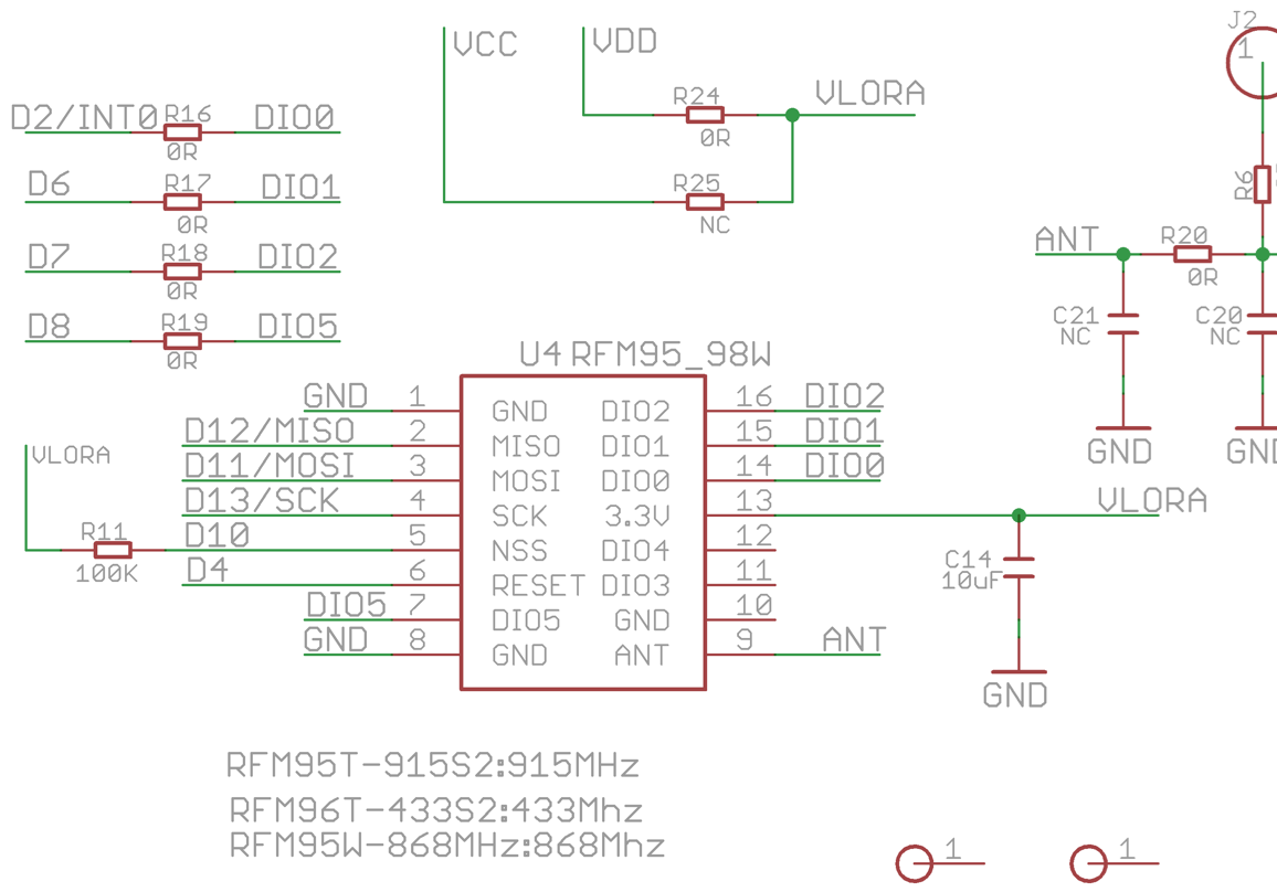
src/boards/bsf_pro8mhzatmega328.h: changed lmic_pinmap (see post #30)
in src/LMIC-node.cpp
//  █ █ █▀▀ █▀▀ █▀▄   █▀▀ █▀█ █▀▄ █▀▀   █▀▄ █▀▀ █▀▀ ▀█▀ █▀█
//  █ █ ▀▀█ █▀▀ █▀▄   █   █ █ █ █ █▀▀   █▀▄ █▀▀ █ █  █  █ █
//  ▀▀▀ ▀▀▀ ▀▀▀ ▀ ▀   ▀▀▀ ▀▀▀ ▀▀  ▀▀▀   ▀▀  ▀▀▀ ▀▀▀ ▀▀▀ ▀ ▀
#include <SPI.h>
#include <Wire.h>

int sensorPin = A2;    // select the input pin for the potentiometer
int sensorValue = 0;  // variable to store the value coming from the sensor
int sensorPowerCtrlPin = 5;

void sensorPowerOn(void)
{
  digitalWrite(sensorPowerCtrlPin, HIGH);//Sensor power on
}
void sensorPowerOff(void)
{
  digitalWrite(sensorPowerCtrlPin, LOW);//Sensor power on
}

const uint8_t payloadBufferLength = 4;    // Adjust to fit max payload length


//  █ █ █▀▀ █▀▀ █▀▄   █▀▀ █▀█ █▀▄ █▀▀   █▀▀ █▀█ █▀▄
//  █ █ ▀▀█ █▀▀ █▀▄   █   █ █ █ █ █▀▀   █▀▀ █ █ █ █
//  ▀▀▀ ▀▀▀ ▀▀▀ ▀ ▀   ▀▀▀ ▀▀▀ ▀▀  ▀▀▀   ▀▀▀ ▀ ▀ ▀▀
//  █ █ █▀▀ █▀▀ █▀▄   █▀▀ █▀█ █▀▄ █▀▀   █▀▄ █▀▀ █▀▀ ▀█▀ █▀█
//  █ █ ▀▀█ █▀▀ █▀▄   █   █ █ █ █ █▀▀   █▀▄ █▀▀ █ █  █  █ █
//  ▀▀▀ ▀▀▀ ▀▀▀ ▀ ▀   ▀▀▀ ▀▀▀ ▀▀  ▀▀▀   ▀▀  ▀▀▀ ▀▀▀ ▀▀▀ ▀ ▀


static volatile uint16_t counter_ = 0;

// uint16_t getCounterValue()
// {
//     // Increments counter and returns the new value.
//     delay(50);         // Fake this takes some time
//     return ++counter_;
// }

// void resetCounter()
// {
//     // Reset counter to 0
//     counter_ = 0;
// }


void processWork(ostime_t doWorkJobTimeStamp)
{
    // This function is called from the doWorkCallback()
    // callback function when the doWork job is executed.

    // Uses globals: payloadBuffer and LMIC data structure.

    // This is where the main work is performed like
    // reading sensor and GPS data and schedule uplink
    // messages if anything needs to be transmitted.


    // begin makerfabs soil moisture sensor

    // Reading temperature or humidity takes about 250 milliseconds!
    // Sensor readings may also be up to 2 seconds 'old' (its a very slow sensor)
    //float humidity = 6.18;//dht.readHumidity();
    // Read temperature as Celsius (the default)

    // int16_t packetnum = 0;  // packet counter, we increment per xmission
    // float temperature=0.0;//
    // float humidity=0.0;

    sensorPowerOn();//
    delay(100);
    sensorValue = analogRead(sensorPin);
    delay(200);

    // if (humiditySensor.available() == true)
    // {
    //     //Get the new temperature and humidity value
    //     temperature = humiditySensor.getTemperature();
    //     humidity = humiditySensor.getHumidity();

    //     //Print the results
    //     Serial.print("Temperature: ");
    //     Serial.print(temperature, 2);
    //     Serial.print(" C\t");
    //     Serial.print("Humidity: ");
    //     Serial.print(humidity, 2);
    //     Serial.println("% RH");

    // }
    //     // Check if any reads failed and exit early (to try again).
    // if (isnan(humidity) || isnan(temperature)) {
    //     Serial.println(F("Failed to read from AHT sensor!"));
    //     //return;
    // }

    delay(100);
    //sensorPowerOff();

    // Serial.print(F("Moisture ADC : "));
    Serial.println(sensorValue);


    //Serial.print(F("Humidity: "));
    //Serial.print(humidity);
    //Serial.print(F("%  Temperature: "));
    //Serial.print(temperature);
    //Serial.println("Humidity is " + (String)humidity);
    //Serial.println("Temperature is " + (String)temperature);

    // String message = "#"+(String)packetnum+" Humidity:"+(String)humidity+"% Temperature:"+(String)temperature+"C"+" ADC:"+(String)sensorValue;
    // Serial.println(message);
    // packetnum++;
    // Serial.println("Transmit: Sending to rf95_server");

    // Send a message to rf95_server

    // uint8_t radioPacket[message.length()+1];
    // message.toCharArray(radioPacket, message.length()+1);

    // radioPacket[message.length()+1]= '\0';

    //Serial.println("Sending..."); delay(10);
    //rf95.send((uint8_t *)radioPacket, message.length()+1);
    //Serial.println("Waiting for packet to complete..."); delay(10);
    //rf95.waitPacketSent();
    // Now wait for a reply
    //uint8_t buf[RH_RF95_MAX_MESSAGE_LEN];
    //uint8_t len = sizeof(buf);

    // ende Makerfabs


    // Skip processWork if using OTAA and still joining.
    if (LMIC.devaddr != 0)
    {
        // Collect input data.
        // For simplicity LMIC-node uses a counter to simulate a sensor.
        // The counter is increased automatically by getCounterValue()
        // and can be reset with a 'reset counter' command downlink message.

        // uint16_t counterValue = getCounterValue();
        ostime_t timestamp = os_getTime();

        #ifdef USE_DISPLAY
            // Interval and Counter values are combined on a single row.
            // This allows to keep the 3rd row empty which makes the
            // information better readable on the small display.
            display.clearLine(INTERVAL_ROW);
            display.setCursor(COL_0, INTERVAL_ROW);
            display.print("I:");
            display.print(doWorkIntervalSeconds);
            display.print("s");
            display.print(" Ctr:");
            display.print(counterValue);
        #endif
        #ifdef USE_SERIAL
            printEvent(timestamp, "Input data collected", PrintTarget::Serial);
            printSpaces(serial, MESSAGE_INDENT);
            // serial.print(F("COUNTER value: "));
            // serial.println(counterValue);
        #endif

        // For simplicity LMIC-node will try to send an uplink
        // message every time processWork() is executed.

        // Schedule uplink message if possible
        if (LMIC.opmode & OP_TXRXPEND)
        {
            // TxRx is currently pending, do not send.
            #ifdef USE_SERIAL
                printEvent(timestamp, "Uplink not scheduled because TxRx pending", PrintTarget::Serial);
            #endif
            #ifdef USE_DISPLAY
                printEvent(timestamp, "UL not scheduled", PrintTarget::Display);
            #endif
        }
        else
        {
            // Prepare uplink payload.
            uint8_t fPort = 10;
            // payloadBuffer[0] = counterValue >> 8;
            // payloadBuffer[1] = counterValue & 0xFF;
            payloadBuffer[0] = sensorValue >> 8;
            payloadBuffer[1] = sensorValue & 0xFF;
            uint8_t payloadLength = 2;

            scheduleUplink(fPort, payloadBuffer, payloadLength);
        }
    }
}


void processDownlink(ostime_t txCompleteTimestamp, uint8_t fPort, uint8_t* data, uint8_t dataLength)
{
    // This function is called from the onEvent() event handler
    // on EV_TXCOMPLETE when a downlink message was received.

    // Implements a 'reset counter' command that can be sent via a downlink message.
    // To send the reset counter command to the node, send a downlink message
    // (e.g. from the TTN Console) with single byte value resetCmd on port cmdPort.

    const uint8_t cmdPort = 100;
    const uint8_t resetCmd= 0xC0;

    if (fPort == cmdPort && dataLength == 1 && data[0] == resetCmd)
    {
        #ifdef USE_SERIAL
            printSpaces(serial, MESSAGE_INDENT);
            serial.println(F("Reset cmd received"));
        #endif
        ostime_t timestamp = os_getTime();
        //resetCounter();
        //printEvent(timestamp, "Counter reset", PrintTarget::All, false);
    }
}


//  █ █ █▀▀ █▀▀ █▀▄   █▀▀ █▀█ █▀▄ █▀▀   █▀▀ █▀█ █▀▄
//  █ █ ▀▀█ █▀▀ █▀▄   █   █ █ █ █ █▀▀   █▀▀ █ █ █ █
//  ▀▀▀ ▀▀▀ ▀▀▀ ▀ ▀   ▀▀▀ ▀▀▀ ▀▀  ▀▀▀   ▀▀▀ ▀ ▀ ▀▀


void setup()
{
    // boardInit(InitType::Hardware) must be called at start of setup() before anything else.
    bool hardwareInitSucceeded = boardInit(InitType::Hardware);

    #ifdef USE_DISPLAY
        initDisplay();
    #endif

    #ifdef USE_SERIAL
        initSerial(MONITOR_SPEED, WAITFOR_SERIAL_S);
    #endif

    boardInit(InitType::PostInitSerial);

    #if defined(USE_SERIAL) || defined(USE_DISPLAY)
        printHeader();
    #endif

    if (!hardwareInitSucceeded)
    {
        #ifdef USE_SERIAL
            serial.println(F("Error: hardware init failed."));
            serial.flush();
        #endif
        #ifdef USE_DISPLAY
            // Following mesage shown only if failure was unrelated to I2C.
            display.setCursor(COL_0, FRMCNTRS_ROW);
            display.print(F("HW init failed"));
        #endif
        abort();
    }

    initLmic();

//  █ █ █▀▀ █▀▀ █▀▄   █▀▀ █▀█ █▀▄ █▀▀   █▀▄ █▀▀ █▀▀ ▀█▀ █▀█
//  █ █ ▀▀█ █▀▀ █▀▄   █   █ █ █ █ █▀▀   █▀▄ █▀▀ █ █  █  █ █
//  ▀▀▀ ▀▀▀ ▀▀▀ ▀ ▀   ▀▀▀ ▀▀▀ ▀▀  ▀▀▀   ▀▀  ▀▀▀ ▀▀▀ ▀▀▀ ▀ ▀

    // Place code for initializing sensors etc. here.

    pinMode(sensorPowerCtrlPin, OUTPUT);
    //digitalWrite(sensorPowerCtrlPin, LOW);//Sensor power on
    sensorPowerOn();
    //pinMode(sensorPin, INPUT);

    // Wire.begin(); //Join I2C bus
    // //Check if the AHT10 will acknowledge
    // if (humiditySensor.begin() == false)
    // {
    //  Serial.println("AHT10 not detected. Please check wiring. Freezing.");
    //     //while (1);
    // }
    // else
    //     Serial.println("AHT10 acknowledged.");

    // resetCounter();

//  █ █ █▀▀ █▀▀ █▀▄   █▀▀ █▀█ █▀▄ █▀▀   █▀▀ █▀█ █▀▄
//  █ █ ▀▀█ █▀▀ █▀▄   █   █ █ █ █ █▀▀   █▀▀ █ █ █ █
//  ▀▀▀ ▀▀▀ ▀▀▀ ▀ ▀   ▀▀▀ ▀▀▀ ▀▀  ▀▀▀   ▀▀▀ ▀ ▀ ▀▀
It is still in a development status.
I removed temperature and humidity as I was going to seal the enclosure to make it outdoor capable and only use the soil moisture sensing functionality.
What is missing: Deep sleep functionality - a must have - I am still reading through the info I have got and try to incorporate this (see post #32 #33)
Observations so far:
- max distance currently not yet acceptable ( I need 900m )
I received a signal when the sensor is 2m above ground but not when on ground (the design of the sensor forces this) - I am going to move my gateway up from currently 2 m above ground to 12m (rooftop) . That might help.
- power supply - 2 AAA batteries - unfortunately the sensor is stopping to work already when the 2 batteries are down to 2.7V ( almost half the battery life left) - not according to the spec. That might change when I get deep sleep up and running (if)
I am curious about your thoughts/plans
Thanks
Eckhard