Thanks Nick,
will read that. That will hopefully answer the question about how to combine 3 variables to be loaded to the payloadBuffer.
But where do I have to put the code that updates the sensor measurements inside the cpp?
Thanks Nick,
will read that. That will hopefully answer the question about how to combine 3 variables to be loaded to the payloadBuffer.
But where do I have to put the code that updates the sensor measurements inside the cpp?
Have you read the extensive instructions that were created with the specially setup sections for adding code?
Thanks Nick for supporting me! I will try to work through the documents more detailed as you proposed.
While doing that I recognized that I might have additional problems upfront:
The serial log looks like:
Device-id:     pro-mini
LMIC library:  Classic [Deprecated]
Activation:    OTAA
Interval:      60 seconds

Clock Error:   30000 ppm (1965)
000000000773:  Event: EV_JOINING

000000000837:  doWork job started

000003750842:  doWork job started

000007500850:  doWork job started
...
And It seems not to get any " Event: EV_TXSTART" nor “Event: EV_JOINED”
The TTS console is telling: “Accept join-request” several times without any Data preview?!
Another problem I assume.
Any thoughts?
You’ve correctly identified that your device isn’t getting the Join Accept so no EV_JOINED.
How far apart is the device & gateway - too close & it can overload the input circuitry which scrambles the message - ideally 3 to 5m and a brick wall between them.
Actually it was 5m away with one brick wall in between, I have extended it now to 10m, 3 walls - no change 
Be aware thay CircuitPython for LoRaWAN uses the TinyLora library under the hood.
TinyLora is not LoRaWAN compliant and cannot handle downlinks and MAC commands and shall therefore not be used with TTN V3.
Only the MCCI LMIC library generates those events. Classic LMIC does not. LMIC-node uses Classic LMIC for 8-bit AVR MCU (see README.md). This explains why you do not see these events.
If the join fails, check if DIO1 is properly connected (see the board’s BSF for details).
Do you have tried to get it working with ABP already? Latter does not depend on DIO1 (only on DIO0).
About the RPI Pico - my plan is to change to Platformio like the Atmega 328p as I would like to use the deep sleep functionality.
About the Atmega328p - I tried ABP before with the LMIC-Node but compiling failed with an error message:
src/LMIC-node.h:110:6: error: #error Do NOT use ABP activation when using the deprecated IBM LMIC framework library. On The Things Network V3 this will cause a downlink message for EVERY uplink message because it does properly handle MAC commands.
?!
Ah, typo in the error message: “it does properly handle MAC commands” should read “it does NOT properly handle MAC commands” instead.
LMIC-node for 8-bit AVR MCU’s, due to their limited memory, does not support MCCI LMIC, only Classic LMIC (IBM LMIC Framework).
Unfortunately latter has its shortcomings, it is no longer maintained and is now deprecated. It should not be used with ABP for TTN V3.
So sorry, for 8-bit AVR MCU, LMIC-node cannot be used for ABP (was not a good suggestion for your AVR board).
RTFM.
Thanks bluejedi for the answer!
Your comment about the BSF brought me the following:
Scheme form my board:Link
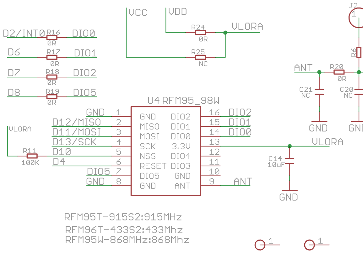
while the BSF for Atmega328p Link
is calling out:
*                SPI/LoRa module     GPIO
 *                ----                ----
 *                MOSI  <――――――――――>  11  (MOSI)
 *                MISO  <――――――――――>  12  (MISO)
 *                SCK   <――――――――――>  13  (SCK)
 *                NSS   <――――――――――>  10  (SS)
 *                RST   <――――――――――>   7
 *                DIO0  <――――――――――>   8
 *                DIO1  <――――――――――>   9
 *                DIO2                 -  Not needed for LoRa.
So I have to change the BSF.h right?
Thanks Guys! That was the problem!
I changed the bsf_pro8mhzatmega328.h to:
const lmic_pinmap lmic_pins = {
    .nss = 10,
    .rxtx = LMIC_UNUSED_PIN,
    .rst = 4,
    .dio = { /*dio0*/ 2, /*dio1*/ 6, /*dio2*/ LMIC_UNUSED_PIN }
and now it works!
LMIC-node

Device-id:     pro-mini
LMIC library:  Classic [Deprecated]
Activation:    OTAA
Interval:      60 seconds

Clock Error:   30000 ppm (1965)
000000000813:  Event: EV_JOINING

000000000877:  doWork job started
000000346684:  Event: EV_JOINED

000000346756:  doWork job started
000000349951:  Input data collected
               COUNTER value: 1
000000350053:  Packet queued
000000668286:  Event: EV_TXCOMPLETE
               Up: 1,  Down: 1
               Downlink received
               RSSI: -72 dBm,  SNR: 9.7 dB
               Port: 0
Now I will try to change the code to get the sensor data integrated . Will report when successful.
Soil sensor now working!
I currently measure 5.5mA power consumption - to high for a battery powered node.
Any thoughts on that how to incorporate deep sleep?
The Supplier of the soil sensor is offering something under : Link but it does not use the LMIC-node?!
Thanks
Eckhard
You can use the low power library for Arduino:
That’s a good start. Low Power can get interesting with LMIC so it may be a good thing for us all to collaborate on a template for LMIC-node
It’s a hardware thing. I remember with ATmega328 and RFM95 were 5µA possible with external Interrupt 1µA. How low can a ATmega4808 with RFM95 go? I see you have a nice test build on your workbench.
About the same, a 4808 has a newer core but it’s basically the same beast. I’ll measure it over the next few days.
Found this looking for a sketch for this that works on TTN with this stick (for demos). Can you share what you have?
Sure.
Preface Info: The most important information I have got from the excellent documentation of the LMIC-node!
I have used Platformio (Visual Studio Node) for this.
I downloaded LMIC-node (see post #14) and changed the following:
platformio.ini: changed device to pro8mhzatmega328 (uncomment line 66)
copied lorawan-key-example.h to lortwan-key.h and added my keys (from my TTN devices - I used OTAA mode)
src/boards/bsf_pro8mhzatmega328.h: changed lmic_pinmap (see post #30)
in src/LMIC-node.cpp
//  █ █ █▀▀ █▀▀ █▀▄   █▀▀ █▀█ █▀▄ █▀▀   █▀▄ █▀▀ █▀▀ ▀█▀ █▀█
//  █ █ ▀▀█ █▀▀ █▀▄   █   █ █ █ █ █▀▀   █▀▄ █▀▀ █ █  █  █ █
//  ▀▀▀ ▀▀▀ ▀▀▀ ▀ ▀   ▀▀▀ ▀▀▀ ▀▀  ▀▀▀   ▀▀  ▀▀▀ ▀▀▀ ▀▀▀ ▀ ▀
#include <SPI.h>
#include <Wire.h>

int sensorPin = A2;    // select the input pin for the potentiometer
int sensorValue = 0;  // variable to store the value coming from the sensor
int sensorPowerCtrlPin = 5;

void sensorPowerOn(void)
{
  digitalWrite(sensorPowerCtrlPin, HIGH);//Sensor power on
}
void sensorPowerOff(void)
{
  digitalWrite(sensorPowerCtrlPin, LOW);//Sensor power on
}

const uint8_t payloadBufferLength = 4;    // Adjust to fit max payload length


//  █ █ █▀▀ █▀▀ █▀▄   █▀▀ █▀█ █▀▄ █▀▀   █▀▀ █▀█ █▀▄
//  █ █ ▀▀█ █▀▀ █▀▄   █   █ █ █ █ █▀▀   █▀▀ █ █ █ █
//  ▀▀▀ ▀▀▀ ▀▀▀ ▀ ▀   ▀▀▀ ▀▀▀ ▀▀  ▀▀▀   ▀▀▀ ▀ ▀ ▀▀
//  █ █ █▀▀ █▀▀ █▀▄   █▀▀ █▀█ █▀▄ █▀▀   █▀▄ █▀▀ █▀▀ ▀█▀ █▀█
//  █ █ ▀▀█ █▀▀ █▀▄   █   █ █ █ █ █▀▀   █▀▄ █▀▀ █ █  █  █ █
//  ▀▀▀ ▀▀▀ ▀▀▀ ▀ ▀   ▀▀▀ ▀▀▀ ▀▀  ▀▀▀   ▀▀  ▀▀▀ ▀▀▀ ▀▀▀ ▀ ▀


static volatile uint16_t counter_ = 0;

// uint16_t getCounterValue()
// {
//     // Increments counter and returns the new value.
//     delay(50);         // Fake this takes some time
//     return ++counter_;
// }

// void resetCounter()
// {
//     // Reset counter to 0
//     counter_ = 0;
// }


void processWork(ostime_t doWorkJobTimeStamp)
{
    // This function is called from the doWorkCallback()
    // callback function when the doWork job is executed.

    // Uses globals: payloadBuffer and LMIC data structure.

    // This is where the main work is performed like
    // reading sensor and GPS data and schedule uplink
    // messages if anything needs to be transmitted.


    // begin makerfabs soil moisture sensor

    // Reading temperature or humidity takes about 250 milliseconds!
    // Sensor readings may also be up to 2 seconds 'old' (its a very slow sensor)
    //float humidity = 6.18;//dht.readHumidity();
    // Read temperature as Celsius (the default)

    // int16_t packetnum = 0;  // packet counter, we increment per xmission
    // float temperature=0.0;//
    // float humidity=0.0;

    sensorPowerOn();//
    delay(100);
    sensorValue = analogRead(sensorPin);
    delay(200);

    // if (humiditySensor.available() == true)
    // {
    //     //Get the new temperature and humidity value
    //     temperature = humiditySensor.getTemperature();
    //     humidity = humiditySensor.getHumidity();

    //     //Print the results
    //     Serial.print("Temperature: ");
    //     Serial.print(temperature, 2);
    //     Serial.print(" C\t");
    //     Serial.print("Humidity: ");
    //     Serial.print(humidity, 2);
    //     Serial.println("% RH");

    // }
    //     // Check if any reads failed and exit early (to try again).
    // if (isnan(humidity) || isnan(temperature)) {
    //     Serial.println(F("Failed to read from AHT sensor!"));
    //     //return;
    // }

    delay(100);
    //sensorPowerOff();

    // Serial.print(F("Moisture ADC : "));
    Serial.println(sensorValue);


    //Serial.print(F("Humidity: "));
    //Serial.print(humidity);
    //Serial.print(F("%  Temperature: "));
    //Serial.print(temperature);
    //Serial.println("Humidity is " + (String)humidity);
    //Serial.println("Temperature is " + (String)temperature);

    // String message = "#"+(String)packetnum+" Humidity:"+(String)humidity+"% Temperature:"+(String)temperature+"C"+" ADC:"+(String)sensorValue;
    // Serial.println(message);
    // packetnum++;
    // Serial.println("Transmit: Sending to rf95_server");

    // Send a message to rf95_server

    // uint8_t radioPacket[message.length()+1];
    // message.toCharArray(radioPacket, message.length()+1);

    // radioPacket[message.length()+1]= '\0';

    //Serial.println("Sending..."); delay(10);
    //rf95.send((uint8_t *)radioPacket, message.length()+1);
    //Serial.println("Waiting for packet to complete..."); delay(10);
    //rf95.waitPacketSent();
    // Now wait for a reply
    //uint8_t buf[RH_RF95_MAX_MESSAGE_LEN];
    //uint8_t len = sizeof(buf);

    // ende Makerfabs


    // Skip processWork if using OTAA and still joining.
    if (LMIC.devaddr != 0)
    {
        // Collect input data.
        // For simplicity LMIC-node uses a counter to simulate a sensor.
        // The counter is increased automatically by getCounterValue()
        // and can be reset with a 'reset counter' command downlink message.

        // uint16_t counterValue = getCounterValue();
        ostime_t timestamp = os_getTime();

        #ifdef USE_DISPLAY
            // Interval and Counter values are combined on a single row.
            // This allows to keep the 3rd row empty which makes the
            // information better readable on the small display.
            display.clearLine(INTERVAL_ROW);
            display.setCursor(COL_0, INTERVAL_ROW);
            display.print("I:");
            display.print(doWorkIntervalSeconds);
            display.print("s");
            display.print(" Ctr:");
            display.print(counterValue);
        #endif
        #ifdef USE_SERIAL
            printEvent(timestamp, "Input data collected", PrintTarget::Serial);
            printSpaces(serial, MESSAGE_INDENT);
            // serial.print(F("COUNTER value: "));
            // serial.println(counterValue);
        #endif

        // For simplicity LMIC-node will try to send an uplink
        // message every time processWork() is executed.

        // Schedule uplink message if possible
        if (LMIC.opmode & OP_TXRXPEND)
        {
            // TxRx is currently pending, do not send.
            #ifdef USE_SERIAL
                printEvent(timestamp, "Uplink not scheduled because TxRx pending", PrintTarget::Serial);
            #endif
            #ifdef USE_DISPLAY
                printEvent(timestamp, "UL not scheduled", PrintTarget::Display);
            #endif
        }
        else
        {
            // Prepare uplink payload.
            uint8_t fPort = 10;
            // payloadBuffer[0] = counterValue >> 8;
            // payloadBuffer[1] = counterValue & 0xFF;
            payloadBuffer[0] = sensorValue >> 8;
            payloadBuffer[1] = sensorValue & 0xFF;
            uint8_t payloadLength = 2;

            scheduleUplink(fPort, payloadBuffer, payloadLength);
        }
    }
}


void processDownlink(ostime_t txCompleteTimestamp, uint8_t fPort, uint8_t* data, uint8_t dataLength)
{
    // This function is called from the onEvent() event handler
    // on EV_TXCOMPLETE when a downlink message was received.

    // Implements a 'reset counter' command that can be sent via a downlink message.
    // To send the reset counter command to the node, send a downlink message
    // (e.g. from the TTN Console) with single byte value resetCmd on port cmdPort.

    const uint8_t cmdPort = 100;
    const uint8_t resetCmd= 0xC0;

    if (fPort == cmdPort && dataLength == 1 && data[0] == resetCmd)
    {
        #ifdef USE_SERIAL
            printSpaces(serial, MESSAGE_INDENT);
            serial.println(F("Reset cmd received"));
        #endif
        ostime_t timestamp = os_getTime();
        //resetCounter();
        //printEvent(timestamp, "Counter reset", PrintTarget::All, false);
    }
}


//  █ █ █▀▀ █▀▀ █▀▄   █▀▀ █▀█ █▀▄ █▀▀   █▀▀ █▀█ █▀▄
//  █ █ ▀▀█ █▀▀ █▀▄   █   █ █ █ █ █▀▀   █▀▀ █ █ █ █
//  ▀▀▀ ▀▀▀ ▀▀▀ ▀ ▀   ▀▀▀ ▀▀▀ ▀▀  ▀▀▀   ▀▀▀ ▀ ▀ ▀▀


void setup()
{
    // boardInit(InitType::Hardware) must be called at start of setup() before anything else.
    bool hardwareInitSucceeded = boardInit(InitType::Hardware);

    #ifdef USE_DISPLAY
        initDisplay();
    #endif

    #ifdef USE_SERIAL
        initSerial(MONITOR_SPEED, WAITFOR_SERIAL_S);
    #endif

    boardInit(InitType::PostInitSerial);

    #if defined(USE_SERIAL) || defined(USE_DISPLAY)
        printHeader();
    #endif

    if (!hardwareInitSucceeded)
    {
        #ifdef USE_SERIAL
            serial.println(F("Error: hardware init failed."));
            serial.flush();
        #endif
        #ifdef USE_DISPLAY
            // Following mesage shown only if failure was unrelated to I2C.
            display.setCursor(COL_0, FRMCNTRS_ROW);
            display.print(F("HW init failed"));
        #endif
        abort();
    }

    initLmic();

//  █ █ █▀▀ █▀▀ █▀▄   █▀▀ █▀█ █▀▄ █▀▀   █▀▄ █▀▀ █▀▀ ▀█▀ █▀█
//  █ █ ▀▀█ █▀▀ █▀▄   █   █ █ █ █ █▀▀   █▀▄ █▀▀ █ █  █  █ █
//  ▀▀▀ ▀▀▀ ▀▀▀ ▀ ▀   ▀▀▀ ▀▀▀ ▀▀  ▀▀▀   ▀▀  ▀▀▀ ▀▀▀ ▀▀▀ ▀ ▀

    // Place code for initializing sensors etc. here.

    pinMode(sensorPowerCtrlPin, OUTPUT);
    //digitalWrite(sensorPowerCtrlPin, LOW);//Sensor power on
    sensorPowerOn();
    //pinMode(sensorPin, INPUT);

    // Wire.begin(); //Join I2C bus
    // //Check if the AHT10 will acknowledge
    // if (humiditySensor.begin() == false)
    // {
    //  Serial.println("AHT10 not detected. Please check wiring. Freezing.");
    //     //while (1);
    // }
    // else
    //     Serial.println("AHT10 acknowledged.");

    // resetCounter();

//  █ █ █▀▀ █▀▀ █▀▄   █▀▀ █▀█ █▀▄ █▀▀   █▀▀ █▀█ █▀▄
//  █ █ ▀▀█ █▀▀ █▀▄   █   █ █ █ █ █▀▀   █▀▀ █ █ █ █
//  ▀▀▀ ▀▀▀ ▀▀▀ ▀ ▀   ▀▀▀ ▀▀▀ ▀▀  ▀▀▀   ▀▀▀ ▀ ▀ ▀▀
It is still in a development status.
I removed temperature and humidity as I was going to seal the enclosure to make it outdoor capable and only use the soil moisture sensing functionality.
What is missing: Deep sleep functionality - a must have - I am still reading through the info I have got and try to incorporate this (see post #32 #33)
Observations so far:
I am curious about your thoughts/plans
Thanks
Eckhard
A common problem for soils sensor and similar use cases - e.g. parking sensors, in ground/pit water meters etc. as you are battling against Freznel Zone effects on RF. Only solution is have sensor on ground and try to get actual ant up above around 1m (not alway practical obviously - 2m is good as you have found!) or mitigate with much higher GW ant placement to increase signal to ground angle of tx… there is a reason you usually see cellular ant mounted at 20-30m+ and rarely lower than 12-15 above local ground level ![]() Early tests and trials with LoRa for water metering test applications (actually in pits with metal lids) in some of the Paris suburbs were done successfully by placing Gw’s/receivers high on local residential appartment block etc (many >>12-20 stories high!) A good quality, well characterised node ant engineered/optimised for such use cases also can help - avoid the common length of wire oft loved by hobbyists and RFM95W users!
Early tests and trials with LoRa for water metering test applications (actually in pits with metal lids) in some of the Paris suburbs were done successfully by placing Gw’s/receivers high on local residential appartment block etc (many >>12-20 stories high!) A good quality, well characterised node ant engineered/optimised for such use cases also can help - avoid the common length of wire oft loved by hobbyists and RFM95W users!
The power-supply seems to be designed for Li-batteries , most of these batteries are empty at 2.7V. Depending on the internal voltage-regulator you can use 3xAAA but first check, wether all components can work with this voltage.
An antenna on the ground is always a problem. As already said, the solution is a separate antenna in a higher position or a gateway looking at the node “from above”.