Descartes, thank you for your response. Below is the information you suggested.
In regards to the Sketch itself, it is based on the sketch provided within the SparkFun hookup guide,
however, that sketch is written for the SX127x chip, with comments for settings, and variable definitions to be changed for the SX126x chip, that I modified.
Click to see the snippet of the serial output log
Starting

SPI1 begin
SPI IOM 3
2077: EV_JOINING
00:00:00.034: engineUpdate[opmode=0x4]
00:00:05.983: engineUpdate[opmode=0x4]
374243: EV_TXSTART
00:00:05.989: engineUpdate[opmode=0x884]
00:00:05.993: TX[mod=LoRa,sf=10,bw=125,cr=4/5,nocrc=0,ih=0,fcnt=0,freq=902.3,pow=30,len=23]: 000000000000000000992700D87ED5B370A1A6241B6250
399063: EV_TXDONE
00:00:06.386: engineUpdate[opmode=0x884]
00:00:11.374: RX_MODE[mod=LoRa,sf=10,bw=500,cr=4/5,nocrc=1,ih=0,freq=923.3,rxtime=711549]
00:00:11.388: WARNING: rxtime is 237 ticks in the past! (ramp-up time 6 ms / 379 ticks)
00:00:11.409: RX: TIMEOUT
00:00:12.377: RX_MODE[mod=LoRa,sf=12,bw=500,cr=4/5,nocrc=1,ih=0,freq=923.3,rxtime=774241]
00:00:12.391: WARNING: rxtime is 237 ticks in the past! (ramp-up time 6 ms / 379 ticks)
00:00:12.449: RX: TIMEOUT
00:00:24.924: engineUpdate[opmode=0x4]
1558018: EV_TXSTART
00:00:24.929: engineUpdate[opmode=0x884]
00:00:24.933: TX[mod=LoRa,sf=10,bw=125,cr=4/5,nocrc=0,ih=0,fcnt=0,freq=911.7,pow=30,len=23]: 000000000000000000992700D87ED5B370178B517D5462
1582841: EV_TXDONE
00:00:25.327: engineUpdate[opmode=0x884]
00:00:30.315: RX_MODE[mod=LoRa,sf=10,bw=500,cr=4/5,nocrc=1,ih=0,freq=927.5,rxtime=1895327]
00:00:30.329: WARNING: rxtime is 243 ticks in the past! (ramp-up time 6 ms / 379 ticks)
00:00:30.349: RX: TIMEOUT
00:00:31.318: RX_MODE[mod=LoRa,sf=12,bw=500,cr=4/5,nocrc=1,ih=0,freq=923.3,rxtime=1958019]
00:00:31.332: WARNING: rxtime is 243 ticks in the past! (ramp-up time 6 ms / 379 ticks)
00:00:31.389: RX: TIMEOUT
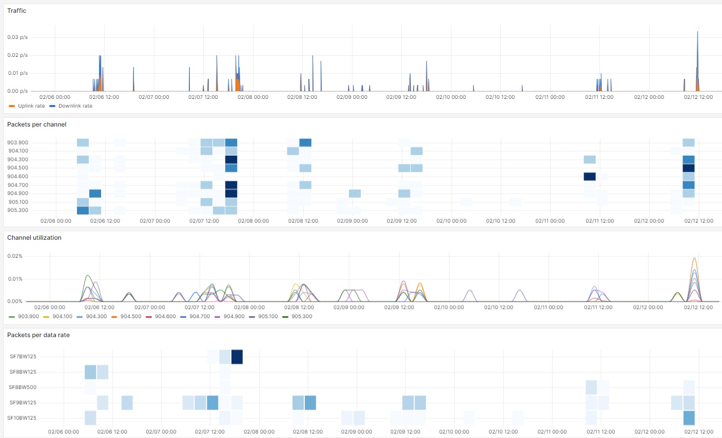
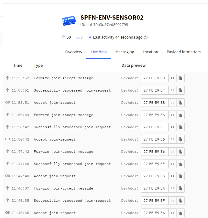
Click to see The TTN device activity log:
I followed the hookup guide for the device at [SparkFun expLoRaBLE Hookup Guide - SparkFun Learn]
Click to see the Sketch for the device
/*******************************************************************************
 * Copyright (c) 2015 Thomas Telkamp and Matthijs Kooijman
 *
 * Permission is hereby granted, free of charge, to anyone
 * obtaining a copy of this document and accompanying files,
 * to do whatever they want with them without any restriction,
 * including, but not limited to, copying, modification and redistribution.
 * NO WARRANTY OF ANY KIND IS PROVIDED.
 *
 * This example sends a valid LoRaWAN packet with payload "Hello,
 * world!", using frequency and encryption settings matching those of
 * the The Things Network.
 *
 * This uses OTAA (Over-the-air activation), where where a DevEUI and
 * application key is configured, which are used in an over-the-air
 * activation procedure where a DevAddr and session keys are
 * assigned/generated for use with all further communication.
 *
 * Note: LoRaWAN per sub-band duty-cycle limitation is enforced (1% in
 * g1, 0.1% in g2), but not the TTN fair usage policy (which is probably
 * violated by this sketch when left running for longer)!

 * To use this sketch, first register your application and device with
 * the things network, to set or generate an AppEUI, DevEUI and AppKey.
 * Multiple devices can use the same AppEUI, but each device has its own
 * DevEUI and AppKey.
 *
 * Do not forget to define the radio type correctly in config.h.
 *
 *******************************************************************************/

#include <basicmac.h>
#include <hal/hal.h>
#include <SPI.h>

// This EUI must be in little-endian format, so least-significant-byte
// first. When copying an EUI from ttnctl output, this means to reverse
// the bytes. For TTN issued EUIs the last bytes should be 0xD5, 0xB3,
// 0x70.
static const u1_t PROGMEM APPEUI[8]={ 0x00, 0x00, 0x00, 0x00, 0x00, 0x00, 0x00, 0x00 };
void os_getJoinEui (u1_t* buf) { memcpy_P(buf, APPEUI, 8);}

// This should also be in little endian format, see above.
static const u1_t PROGMEM DEVEUI[8]={ 0x99, 0x27, 0x00, 0xD8, 0x7E, 0xD5, 0xB3, 0x70 };
void os_getDevEui (u1_t* buf) { memcpy_P(buf, DEVEUI, 8);}

// This key should be in big endian format (or, since it is not really a
// number but a block of memory, endianness does not really apply). In
// practice, a key taken from ttnctl can be copied as-is.
// The key shown here is the semtech default key.
static const u1_t PROGMEM APPKEY[16] = { 0xB5, 0x7B, 0x4F, 0xFC, 0x98, 0x60, 0x66, 0x2D, 0x6B, 0xF8, 0x40, 0xB3, 0x82, 0xC4, 0x19, 0xDF };
void os_getNwkKey (u1_t* buf) {  memcpy_P(buf, APPKEY, 16);}

// The region to use, this just uses the first one (can be changed if
// multiple regions are enabled).
u1_t os_getRegion (void) { return LMIC_regionCode(0); }

// Schedule TX every this many milliseconds (might become longer due to duty
// cycle limitations).
const unsigned TX_INTERVAL = 60000;

// Timestamp of last packet sent
uint32_t last_packet = 0;

// When this is defined, a standard pinmap from standard-pinmaps.ino
// will be used.  If you need to use a custom pinmap, comment this line
// and enter the pin numbers in the lmic_pins variable below.
// #define USE_STANDARD_PINMAP

#if !defined(USE_STANDARD_PINMAP)
// All pin assignments use Arduino pin numbers (e.g. what you would pass
// to digitalWrite), or LMIC_UNUSED_PIN when a pin is not connected.
const lmic_pinmap lmic_pins = {
    // NSS input pin for SPI communication (required)
    .nss = D36,
    // If needed, these pins control the RX/TX antenna switch (active
    // high outputs). When you have both, the antenna switch can
    // powerdown when unused. If you just have a RXTX pin it should
    // usually be assigned to .tx, reverting to RX mode when idle).
    //
    // The SX127x has an RXTX pin that can automatically control the
    // antenna switch (if internally connected on the transceiver
    // board). This pin is always active, so no configuration is needed
    // for that here.
    // On SX126x, the DIO2 can be used for the same thing, but this is
    // disabled by default. To enable this, set .tx to
    // LMIC_CONTROLLED_BY_DIO2 below (this seems to be common and
    // enabling it when not needed is probably harmless, unless DIO2 is
    // connected to GND or VCC directly inside the transceiver board).
    .tx = LMIC_CONTROLLED_BY_DIO2,
    .rx = LMIC_UNUSED_PIN,
    // Radio reset output pin (active high for SX1276, active low for
    // others). When omitted, reset is skipped which might cause problems.
    .rst = D44,
    // DIO input pins.
    //   For SX127x, LoRa needs DIO0 and DIO1, FSK needs DIO0, DIO1 and DIO2
    //   For SX126x, Only DIO1 is needed (so leave DIO0 and DIO2 as LMIC_UNUSED_PIN)
    .dio = {/* DIO0 */ LMIC_UNUSED_PIN, /* DIO1 */ D40, /* DIO2 */ LMIC_UNUSED_PIN},
    // Busy input pin (SX126x only). When omitted, a delay is used which might
    // cause problems.
    .busy = D39,
    // TCXO oscillator enable output pin (active high).
    //
    // For SX127x this should be an I/O pin that controls the TCXO, or
    // LMIC_UNUSED_PIN when a crystal is used instead of a TCXO.
    //
    // For SX126x this should be LMIC_CONTROLLED_BY_DIO3 when a TCXO is
    // directly connected to the transceiver DIO3 to let the transceiver
    // start and stop the TCXO, or LMIC_UNUSED_PIN when a crystal is
    // used instead of a TCXO. Controlling the TCXO from the MCU is not
    // supported.
    .tcxo = LMIC_UNUSED_PIN,
};
#endif // !defined(USE_STANDARD_PINMAP)

void onLmicEvent (ev_t ev) {
    Serial.print(os_getTime());
    Serial.print(": ");
    switch(ev) {
        case EV_SCAN_TIMEOUT:
            Serial.println(F("EV_SCAN_TIMEOUT"));
            break;
        case EV_BEACON_FOUND:
            Serial.println(F("EV_BEACON_FOUND"));
            break;
        case EV_BEACON_MISSED:
            Serial.println(F("EV_BEACON_MISSED"));
            break;
        case EV_BEACON_TRACKED:
            Serial.println(F("EV_BEACON_TRACKED"));
            break;
        case EV_JOINING:
            Serial.println(F("EV_JOINING"));
            break;
        case EV_JOINED:
            Serial.println(F("EV_JOINED"));

            // Disable link check validation (automatically enabled
            // during join, but not supported by TTN at this time).
            LMIC_setLinkCheckMode(0);
            break;
        case EV_RFU1:
            Serial.println(F("EV_RFU1"));
            break;
        case EV_JOIN_FAILED:
            Serial.println(F("EV_JOIN_FAILED"));
            break;
        case EV_REJOIN_FAILED:
            Serial.println(F("EV_REJOIN_FAILED"));
            break;
            break;
        case EV_TXCOMPLETE:
            Serial.println(F("EV_TXCOMPLETE (includes waiting for RX windows)"));
            if (LMIC.txrxFlags & TXRX_ACK)
              Serial.println(F("Received ack"));
            if (LMIC.dataLen) {
              Serial.print(F("Received "));
              Serial.print(LMIC.dataLen);
              Serial.println(F(" bytes of payload"));
            }
            break;
        case EV_LOST_TSYNC:
            Serial.println(F("EV_LOST_TSYNC"));
            break;
        case EV_RESET:
            Serial.println(F("EV_RESET"));
            break;
        case EV_RXCOMPLETE:
            // data received in ping slot
            Serial.println(F("EV_RXCOMPLETE"));
            break;
        case EV_LINK_DEAD:
            Serial.println(F("EV_LINK_DEAD"));
            break;
        case EV_LINK_ALIVE:
            Serial.println(F("EV_LINK_ALIVE"));
            break;
        case EV_SCAN_FOUND:
            Serial.println(F("EV_SCAN_FOUND"));
            break;
        case EV_TXSTART:
            Serial.println(F("EV_TXSTART"));
            break;
        case EV_TXDONE:
            Serial.println(F("EV_TXDONE"));
            break;
        case EV_DATARATE:
            Serial.println(F("EV_DATARATE"));
            break;
        case EV_START_SCAN:
            Serial.println(F("EV_START_SCAN"));
            break;
        case EV_ADR_BACKOFF:
            Serial.println(F("EV_ADR_BACKOFF"));
            break;

         default:
            Serial.print(F("Unknown event: "));
            Serial.println(ev);
            break;
    }
}

void setup() {
    Serial.begin(115200);

    // Wait up to 5 seconds for serial to be opened, to allow catching
    // startup messages on native USB boards (that do not reset when
    // serial is opened).
    unsigned long start = millis();
    while (millis() - start < 5000 && !Serial);

    Serial.println();
    Serial.println();
    Serial.println(F("Starting"));
    Serial.println();

    // LMIC init
    os_init(nullptr);
    LMIC_reset();

    // Enable this to increase the receive window size, to compensate
    // for an inaccurate clock.  // This compensate for +/- 10% clock
    // error, a lower value will likely be more appropriate.
    //LMIC_setClockError(MAX_CLOCK_ERROR * 10 / 100);

    // Start join
    LMIC_startJoining();

    // Make sure the first packet is scheduled ASAP after join completes
    last_packet = millis() - TX_INTERVAL;

    // Optionally wait for join to complete (uncomment this is you want
    // to run the loop while joining).
    while ((LMIC.opmode & (OP_JOINING)))
        os_runstep();
}

void loop() {
    // Let LMIC handle background tasks
    os_runstep();

    // If TX_INTERVAL passed, *and* our previous packet is not still
    // pending (which can happen due to duty cycle limitations), send
    // the next packet.
    if (millis() - last_packet > TX_INTERVAL && !(LMIC.opmode & (OP_JOINING|OP_TXRXPEND)))
        send_packet();
}

void send_packet(){
    // Prepare upstream data transmission at the next possible time.
    uint8_t mydata[] = "Hello, world!";
    LMIC_setTxData2(1, mydata, sizeof(mydata)-1, 0);
    Serial.println(F("Packet queued"));

    last_packet = millis();
}