No, I don’t think. I have the same result with a module that was only used with a ceramic antenna.
Something easy to miss with these is that the Lambda62C - the ones with the shield can DO NOT have the antenna pathway connected to pin 1, but only to the u.fl connector where they hope you’ll attach the exact antenna used in the module cert.
I’m getting drastically better results using the u.fl connector, granted pin 1 is currently going into a breadboard with the others and would have huge capacitance to adjacent ground, so I should try clipping that to solder just an entenna, but it looks like C20 is not installed to enable pin 1.
I also feel like I have the RF switch working correctly via DIO2 to the TX switch and currently software (but eventually an inverter) driving the RX switch high the rest of the time.
Modules I use don’t have UFL connector. Of course, DIO2 is driven and I have verified that TX and RX switch signals have expected values.
Just to be sure: Your module has a green and a blue dot?
Yes. Green and blue dots (and a red on SX1262).
Another idea: what happens if you connect the (monopole) antenna to the small pad that is between the two larger pads (SK2)?
Which one ? The center pad of UFL connector ?
Yes, the center pad.
I have soldered an antenna directly on center pad. Same result. New test: I have soldered an antenna before RF switch. No change on RSSI (-102 dBm, expected value -45 dBm).
RSSI isn’t measured in dBm… really its a relative figure in dB referenced to just about nothing.
But apart from that, your experiences mismatch mine - and I’m still using intentionally low transmit power until the antenna switch situation is permanently solidified.
Perhaps you should get some magnification and see if C20 is installed or not - it’s pretty clearly labeled in the test report photos, and in a no-shield can module where it would allegedly be installed there’s no obstacle to seeing it.
You might also need to validate that your code is correctly setting the transmit power level, and that your power situation can actually support that. Underpowering the chip during transmit would not only not achieve the desired output, it would result in broadband splatter due to compression if not outright clipping.
Well, I did suggest it a while back, but I dont think you will progress much on this until you can measure the actual transmit power …
I have done some measurements. Current is around 45 mA when module emits @ 14 dBm (expected value given in datasheet) and I have directly connected pin 1 on a level meter (peak detection). RSSI given by my base station is the real value in dBm. I will try to do some other tests with a spectrum analyzer.
C20 is installed and don’t forget I have soldered a lambda/4 antenna before RF switch (and before C20).
In my first message, you have a transaction between CPU and SX1262. I have analyzed this transaction (and some others) and I don’t see where I could done a mistake.
It’s really not. RSSI is relative, not referenced to anything absolute, and without any absolute meaning after antenna-to-antenna coupling.
You could try writing a script to do a lot of transmit trials in a situation in a situation a a few meters away where you walk out of the area so that nothing gets bumped. For each transmit power level supported by the hardware, do about a dozen transmissions, but do them in random order. Then collect the uncalibrated gateway RSSI’s and plot them as a point cloud against teach other, commanded power vs receive RSSI (you could put the commanded power in the payload to make correlation easy).
Please have a look at Semtech “Corecell gateway Reference design EU version Performance Report Rev. 1.0” chapter 9.3 ff. Maybe we should tell Semtech that there is something wrong (or is it right??).
I am very sorry, but in the moment I have no clue whats going on with your module. 45mA should be ok for 14dBm but the RF seems to disappear somewhere.
If you have a ‘standard’ LoRa device, with the same antenna, that you can program for 14dBm then a nearby spectrum analyser or even cheap SDR, might give you a comparative result.
Unfortunately measuring the current consumption may not tell you much at all, if the antenna was a 50ohm load for instance, the current used might well be appropriate, but the actual radiated power would be very close to very little.
Nope. RSSI is a convenience metric. It’s NOT test equipment. It’s relative only - the units are at best dB"something example unique" NOT dBm.
And when the coupling is two antenna in a casual experiment, even that is in doubt.
That’s one of the reasons they need to try transmitting at a variety of power levels without even having their body present in the near field, and plot command transmit power over receive level in a large enough number of trials to really see what’s going on.
If after plotting a few hundred data points there’s a sharp and clear falloff in receive level at some increase in transmit power, then investigation can look into things like if the power register is being incorrectly set, if the power supply is incapable of that, etc.
Also steps should be taken to be sure that the receive frequency matches the command transmit frequency, and isn’t being confused by weak bleedover onto a different channel when the RX front end is funadmentally overloaded.
See figures 4-8, 4-9, 4-10 in the data sheet, think about the overcurrent protection register. make sure SetPAConfig is using an appropriate set of values for an SX1262 (vs 1261) and that the fine tuning value in SetTxParams is one for the mode being used, and not for the other mode.
Some constatations.
First one : RSSI returned by base station seems to be expected received level in dBm. This value is always (I have tried several distances between device and base station) RF power - free space losses. Of course, RF power measurement is done in lambda62 pin 1 with a level meter.
Second one : SetPAConfig and SetTxParams are set to emit 14 dBm. I have checked hexadecimal values sent to SX1262. I have done some other tests with 0 dBm. Only one difference : RSSI returned by base station is 14 dB lower.
Best regards,
JB
I will try as soon as possible. My spectrum analyzer should be sent back by Agilent next week.
I come back. I have done some measurements with my HP 8592B.
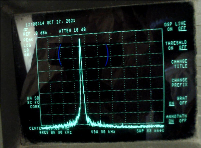
Center 868 MHz, span 10 MHz
This measurement was done with a coaxial cable directly connected between Lambda62’s pin 1 and 2 (Rf output and ground) and when power output is set to 14 dBm. Of course, antenna was removed. Power was very similar to power I have found with my level meter.
I have checked my LoRaWan library and sent to serial console all transactions between CPU and SX1262:
set radio reset: ticks=7484
// GetIrqStatus $12 + NOP // RFU + Status
W1200
R0000
clear radio reset: ticks=7508
W1200
R0000
// SetSleep $84 + cold start + RTC timeout disable
W8400
W1200
R0000
W1200
R0000
// SetRegulatorMode $96 + only LDO used for all modes
W9600
// SetDIO2AsRfSwitchCtrl $9D + enable
W9D01
// SetStandby $80 + STDBY_XOSC
W8001
W1200
R0000
// SetPacketType $8A + LORA
W8A01
// SetDioIrqParams $08 + enable all interrupts
W080000000000000000
// SetRX $82 + single mode
W82000000
listen for entropy: ticks=71925
W1200
R0000
// ReadRegister $1D Addr 0819 + NOP (32 bits random number)
W1D081900
RCE4C999F
// ClearIrqStatus $02 + clear all interrupts
W02FFFF
// SetSleep $84 + cold start + RTC timeout disable
W8400
read entropy: ticks=71941 entropy=2677624014
W1200
R0000
OTAA is pending
add dither to otaa: ticks=72008 delay=1032
W1200
R0000
W1200
R0000
W1200
R0000
W1200
R0000
...
W1200
R0000
W1200
R0000
W9600
W9D01
W8001
W1200
R0000
W1200
R0000
W1200
R0000
TX power : 14 dbm
W8A01
// CalibrateImage 863-870 MHz
W98D7DB
// SetPaConfig $95 + paDutyCycle=2 + hpMax=2 + SX1262 + $01
W9502020001
// SetTxParams $8E + $0E (14 dBm) + 200 us rise time
W8E0E04
// SetufferBaseAddress $8F + TxBase $00 + RxBase $00
W8F0000
// SetRfFrequency
W863644CCCC
// WriteBuffer $0E
W0E00000F315CEE948A4D0457EF13000BA304000000A05C207F
// SetModulationParams
W8B07040100
// SetPacketParams
W8C000800170100
// SetDioIrqParams
W080001000100000000
// WriteRegister LoRa Sync Word MSB Public Network
W0D07403444
// SetTx
W83000000
tx begin
ticks=73124 freq=868300000 power=0  bw=125000 sf=7 size=23
W1200
R0000
...
W1200
R0000
W1200
R0001
Interrupt TX
W1200
R0001
offtime=100
W02FFFF
W8404
tx complete
ticks=73201
W1200
R0000
W1200
R0000
...
W1200
R0000
W8A01
W8F0000
W863644CCCC
W8B07040100
W8C000800FF0001
W080202020200000000
W0D07403444
WA082
W82000000
rx1 slot
ticks=78149 timeout=130 lag=2 freq=868300000 bw=125000 sf=7
W1200
R0000
...
W1200
R0200
Interrupt timeout
W1200
R0200
...
W1200
R0000
channel is ready
W1200
R0000
W1200
R0000
...
W1200
R0000
W8A01
W8F0000
W8636586666
W8B0C040101
W8C000800400001
W080202020200000000
W0D07403444
WA00A
W82000000
rx2 slot
ticks=79124 timeout=10 lag=3 freq=869525000 bw=125000 sf=12
W1200
R0000
W1200
R0200
Interrupt timeout
W1200
R0200
W02FFFF
W8400
W1200
R0000
W1200
R0000
...
W1200
R0000
waiting to retry OTAA
W1200
R0000
add dither to otaa: ticks=79910 delay=25861
W1200
R0000
W1200
R0000
...
R: read + hexadecimal data
W: write + hexadecimal data
Best regards,
JB