The GP901 C has a Frequency Band of 870-960 MHz where the GP868 C has 835-900 MHz.
I think the GP868 is better suited for Lora in Europe.
Yes, if you have managed to increase c - you’d better prepare the universe  What link of Fabiens are you referring to exactly? I’m trying to gain access to a radio lab here over the student holiday period. Annoyingly we did just build an array which was incredible at about 550M and then we scaled it to 868MHz - I’ve lost the paperwork but the unit is up on the roof. @loratracker has achieved some remarkable results too (but is currently side-tacked, deep in a local, (unused), railway tunnel proving that the Semtech chip has a noise issue).
Here is the link to the two different designs. its on the IRNAS GitHub site https://github.com/IRNAS/ttn-irnas-gw
@dicktonyboy, hope you can find the paperwork for the converted 550M antenna. Guess you’ll be shimmying up a drain pipe to measure.  Over the weekend I will also try a Coaxial Colinear, bit fiddly to build but hope the VSWR match is better than the 2:1 in Fabien’s modelling work. If it looks promising, I’ll test the gain and pattern.
So a question for @BoRRoZ and @Charles to see how you guys found the Rak antenna, the fiberglass one you both ordered and discussed in the bargain basement thread?
I hope to deploy some more gateways using @Charles’s pcb to integrate Rak831’s with Pi Zeros. I ordered an antenna with some Rak831’s so would be interested in data on tuning or performance?
Thanks gentlemen!
Garry
https://m.aliexpress.com/item/32852314761.html?trace=storeDetail2msiteDetail
I just received one last week but I haven’t done any testing yet…
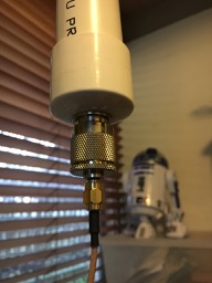
My gateways have SMA pigtails and the RAK antenna is delivered with an RP-SMA connector, so I need some additional bits to swap easily…
I found some bits… ![]()
will try to test (again) today (weekend ![]() ), last time all the graphs went wrong
), last time all the graphs went wrong
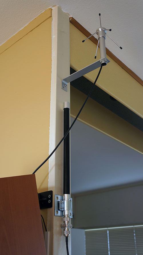
Just installing the Siro GP868 C this week, very well built piece of kit
@dicktonyboy. Just built an 868 MHz colinear antenna to compare with the modelling you posted. Get the exact same shape VSWR curve as per the simulation. Min VSWR is 2.1 but instead of it being around 860-870MHz mine has a minima at 840 MHz. Followed the Tips and could not change the resonant frequency by changing the size of the “last loop”. By that I assume the top loop. Going to see if the “last loop” is the bottom loop which I expect will change the resonant frequency. Just going to solder a “shorting link” to bypass some of the loop and adjust its position to tune to the required frequency.
Hi All,
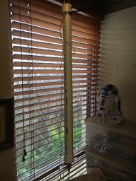
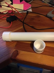
As winter sets in in Australia I have been noticing my receive levels going down, from RSSI’s of 76 to now 88, very confusing. I pulled down my colinear 915Mhz antenna and found it was full of water. As you will notice from the picture the antenna is housed in a high pressure PVC pipe with caps at either end. I cant work out where the water got in.
How do others seal their antennas? What is best practice?
Chris
@cdann, are the pvc pipe caps solvent welded to the tube or just press fitted? Also, how does the cable enter, via a compression gland? Are there any other penetrations, eg for radials etc. I always recommend using self vulcanising / self amalgamating tape on antenna connectors to form a water tight seal. You can use the same tape to seal between the PVC pipe and the antenna cable where the cable enters the tube. Bunnings sell this as a Silicon Self-Fusing tape. If you post some close up photos of the penetrations into the PVC tube, we may be able to provide more detailed answer.
Test results are in. Obtained a VSWR of 1.2:1 and was able to tune the antenna very easily. Its a coaxial dipole consisting of quarter wavelength at the bottom, followed by 8 half wavelength sections stacked above. Built from RG58CU I assumed a Velocity Factor of 0.66. Tuned by trimming the top half wavelength piece of coax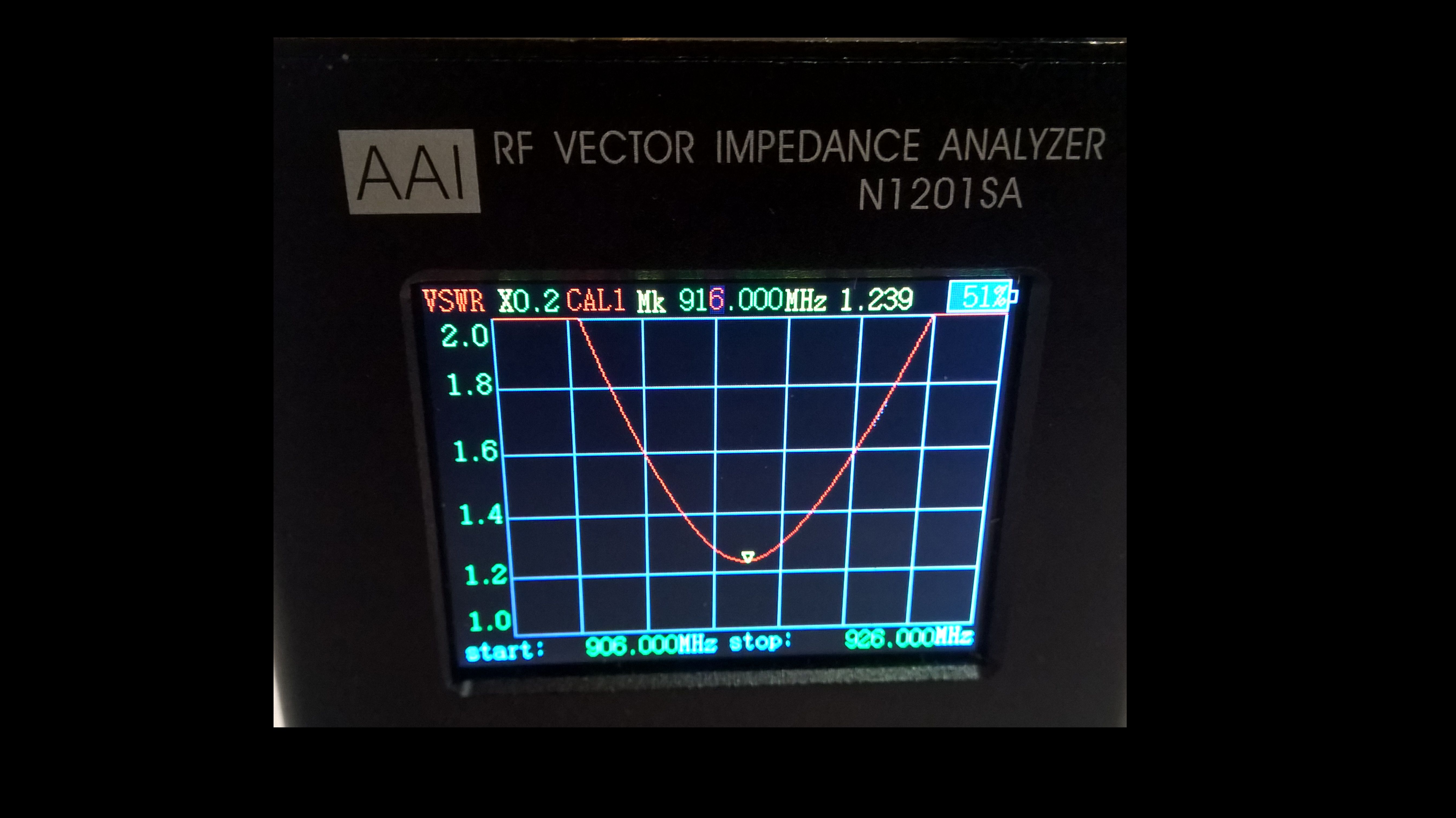 Next step is to check its gain but I expect it will be 6 or so dBi.
1 Like
Did you also use radials as groundplane? I remember somebody else built a similar antenna but with 4 radials.
Hi Tony,
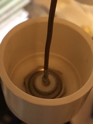
Thanks for your rapid response. No due to the ongoing changes I have not welded anything at this point. The only penetration is for the n-type connector located on the bottom of the antenna. It is a snug fit. It did not seem necessary to do more than press fit, clearly I was wrong. I have attached some closeup pictures. Thanks for your advise on silicon tape.
Chris
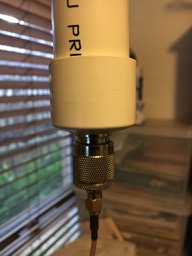
its common for water to enter a Waterproof enclosure, even one with rubber seals. As the enclosure heats and cools the air pressure inside raises and lowers. If the seal is not strong enough the drop in air pressure will suck air past the seal and any water sitting on the seal will be sucked in. it effectively pumps water into the enclosure. I suspect water sitting on the bottom fitting (which is not glued) is being sucked inside the tube. You could solvent weld this joint and leave the top one loose. There is another option and that’s to glue the top cap and put a pair of threaded fittings between the bottom of the pipe and the bottom cap, this would give you access to the bottom of the pipe again. Just seal the threads with plumbers tape. I would also apply self sealing tape around the bottom of the pipe and wind it all the way over the connectors all the way to the coax cable. I’d also suggest you don’t use small coax outside as its hard to apply tape around such a small diameter. Use a larger diameter coax with N-Type connectors and make the N-Type to SMA conversion at the back of the gateway board with a short (100mm tail) Large diameter coax will also have lower losses.
Hope this helps
1 Like
Yes, 4 radials at 1/4 wavelength. since there is no dielectric on the radials the velocity factor = 1. they are also horizontal, no need to downtilt at 45 degrees.
1 Like
Any building process photo?
I’m very curious … let us know if you like it or not 
what I’ve seen from pictures its a pretty little gp antenna
Would not even trying to make the bottom waterproof, but in stead make 2 small holes so water can drain work? Or would that result in condensation along the inside of the pipe at times?
@kersing, you are correct, a couple of holes in an enclosure eliminates the root cause which is the pressure difference. Have done this myself as it allows anything to drain away. Just need to evaluate if the items inside are subject to corrosion with a bit of moisture. There won’t be standing water but there will be higher humidity. What is really important is to seal the coax connectors as the dielectric is often gas filled plastic and the plastic may be hydroscopic and adsorb moisture as well as the gas filled holes can accumulate moisture. Have had experience on commercial radio sites of pulling the RF connector off the end of a coax and water runs out  No wonder the radios performance was affected!!
1 Like