Sorry, my typo. I wanted to say that the gain was relatively low and the front to back ratio poor. I guess if you would want such a setup to hunt for nodes you would benefit more if you would have an antenna like a HB9CV or a biquad antenna with better front-to-back ratio…
1 Like
I want to build a mobile device So no yagi’s.
Tnx… I guess I will just have to test a few things myself first 

hb9cv 
Hopefully we get our next week and maybe repeat your experimental for the 868 band
2 Likes
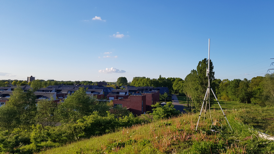
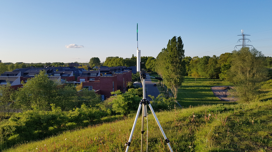
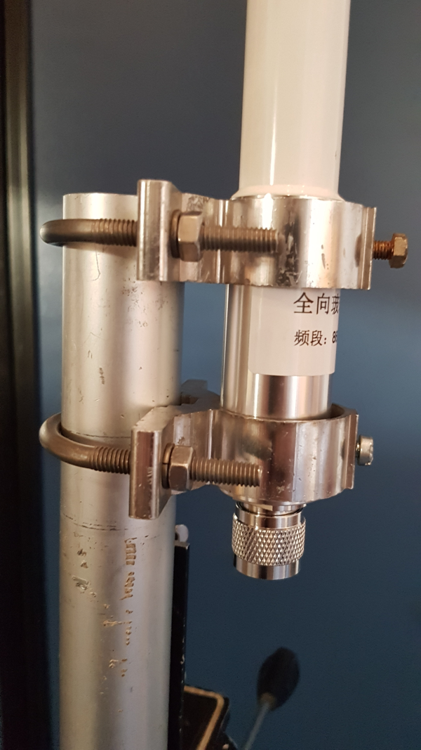
And there he is! Installed on this temporary tripod for coming measurements.
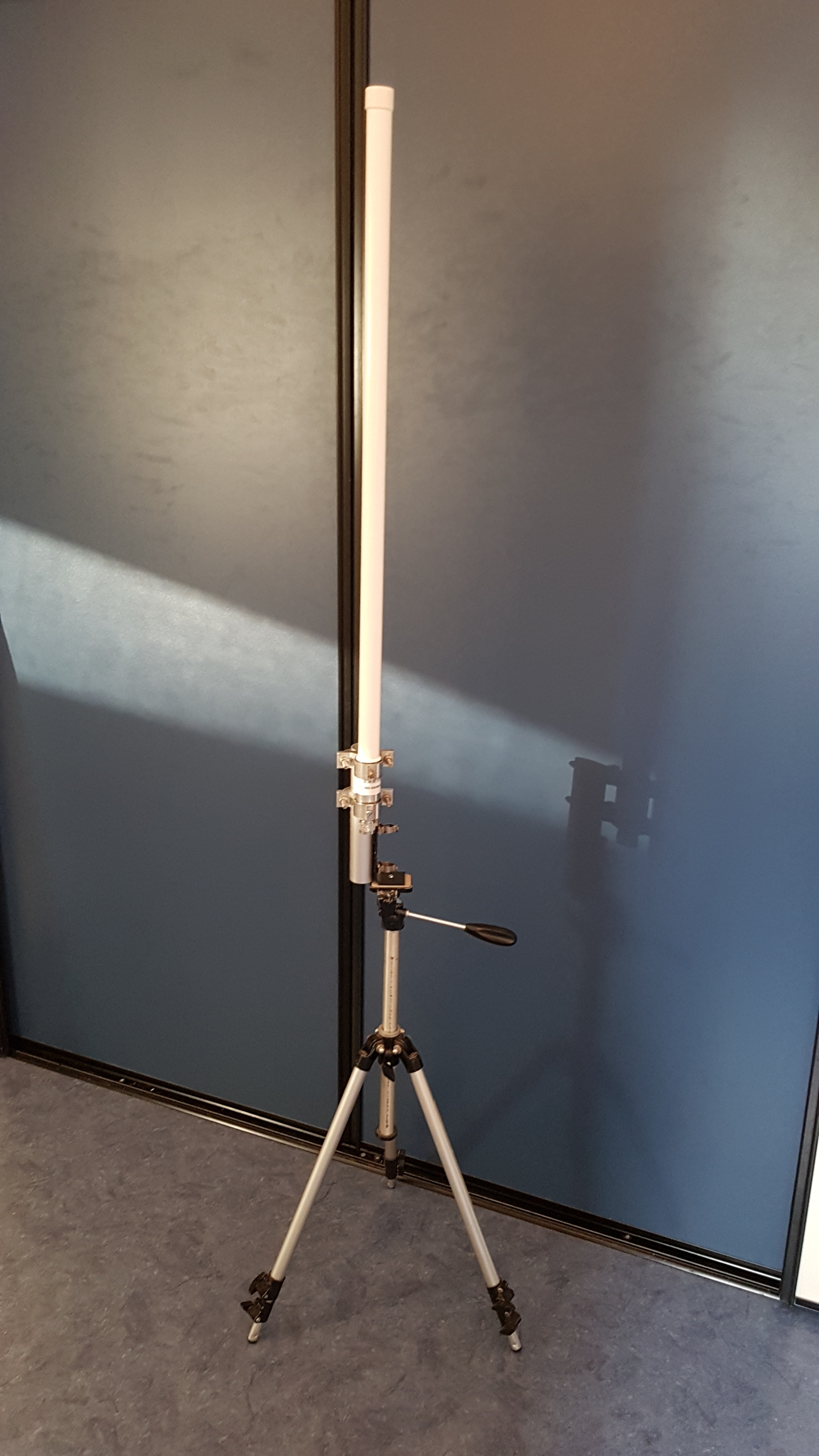
Only problem I had was that I cannot install the antenna proprely with the provided clamps. No idea how RAK thinks it should work. Therefore I used the clamps of an old chineese VHF/UHF antenna.

3 Likes
Love the RAK test reports, all sorts of details inc patterns vs frequency,
Not just the basic meaningless one “gain” value - often made up to appear very high, although like @BoRRoZ said high gains may even be bad if pattern is in the wrong direction…
Can’t wait to test this one.
You raise an interesting point ![]() . With such a wide range of mounting arrangements used on different sites the antenna supplier hasn’t a clue on how the antenna will be installed.
. With such a wide range of mounting arrangements used on different sites the antenna supplier hasn’t a clue on how the antenna will be installed.
For example, its common to mount to a vertical tube but then what’s it’s diameter? It could be a outrigger from a tower and be a horizontal tube (again what size)? Alternatively it could be a bracket secured to a structure like a chimney.
Reflecting on your comment I realised I tossed the clamps that arrived with my antenna on a pile of similar bits and pieces as I build my own clamps. I prefer either stainless steel hardware or Hot Dip Galvanised bolts, nuts and clamps rather than the electroplated versions which rust very quickly. (Example The BIG and SMALL ANTENNA topic part 1 - #451 by BoRRoZ ) I can get a range of clamps sizes from car exhaust suppliers and fabricate from there.
I wonder if there is an opportunity to design and sell a set of universal antenna clamps for Lora systems?
1 Like
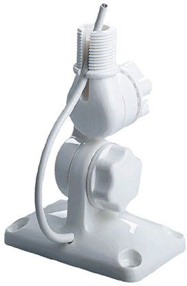
this design is used on boats
this (dutch) webshop has a lot of material
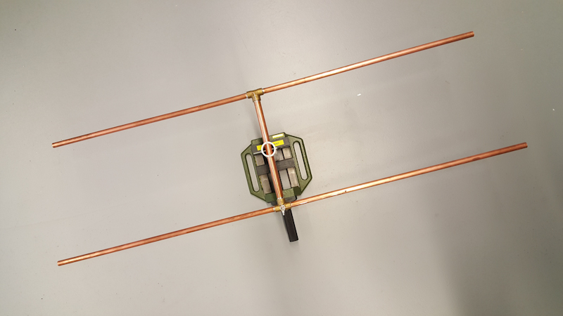
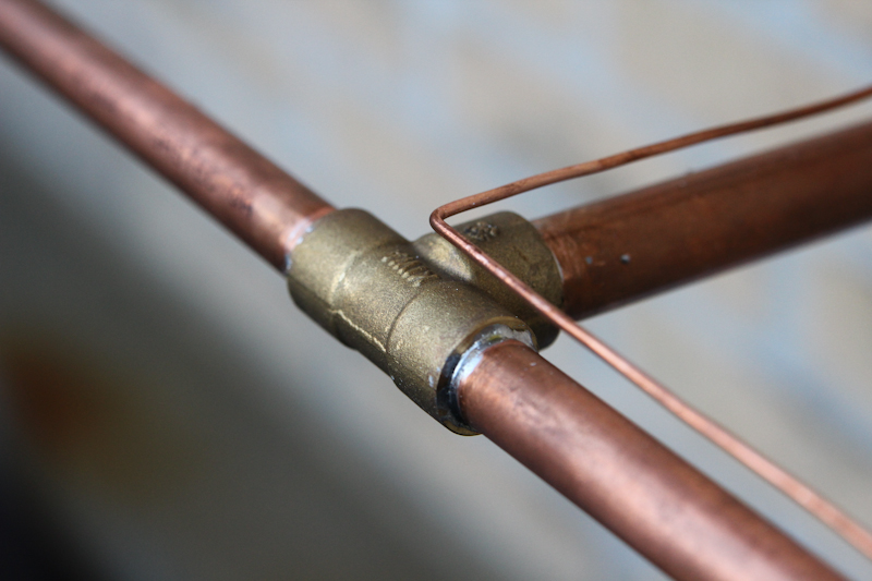
I contacted RAK for radiation patterns and got als the document as linked to by @jmarcelino. In this document I found the intended mounting for the antenna and the brackets. I have reproduced this mounting using “aluminum corner profile” (not sure about the translation from “aluminium hoekprofiel”).
It works but I have observed potentional stability issues. It could result in metal fatigue of the aluminium pice.
I normally try to keep the antenna and support pole as close as possible. This is the type of clamp system I often fabricate. By selecting clamp sizes to suit, the same design works on almost any size pole and any size antenna.
I know there are better designs but it’s quick to fabricate.
1 Like
From the document I get the impression they use two clamps on the antenna, one below the other. That would reduce potential stability issues (based on my experience with other antennas)
Strange, looked at the pdf again and just seeing one bracket. I could have sworn I’ve seen a diagram with two of them somewhere, maybe a different antenna.
1 Like
You are correct, you are not going crazy, there are two clamps shown on their Shop website Fiber Glass Antenna | LoRa High Gain Antenna | Long Range Frequency Antenna
RAK have now set the benchmark for information that should be provided by any antenna manufacturer. A updated version of the report has just been released which simplifies the information for someone with little antenna knowledge. The polar plots have been rotated with an overlay of the antenna to clearly show the vertical and horizontal radiation patterns.
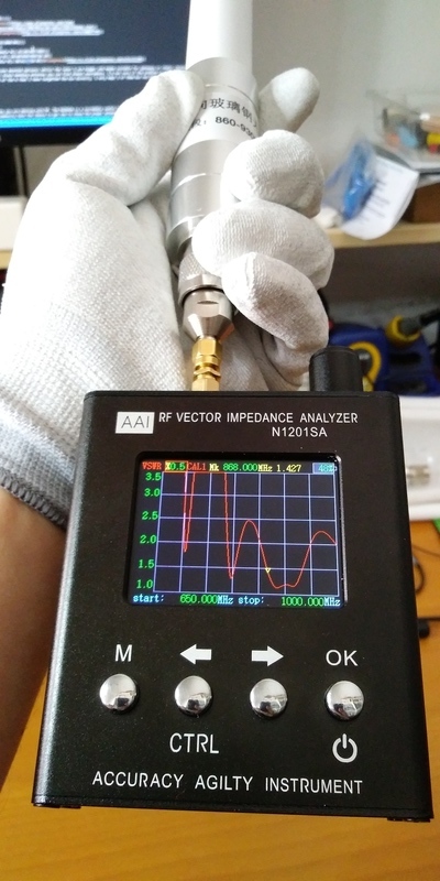
I received mine (the new RAK 80cm 5.6dBi antenna) yesterday and tested it with the N1201SA. The results are pretty good and match those from the datasheet that show that the antenna is slightly better adapted to work at 915Mhz than 868MHz.
Actually I was writing a post comparing different antennas I happen to have around: Analyze your antennas using an AAI N1201SA.
Some pics:
5 Likes
Last week I have evaluated the RAK 6,1 dBi beta antenna. I evaluated mechanical, S11 (reflection), antenna gain, and radiation pattern. These are my observations and conclusion.
Mechanical
The antenna is delivered with 2 clamps for installation. while I initially did not know how they should be used I eventually found a hint in the document “RAK_860-930MHz_5.8dBi_Fiberglass_Antenna_Specification.pdf” that was published earlier in this thread.
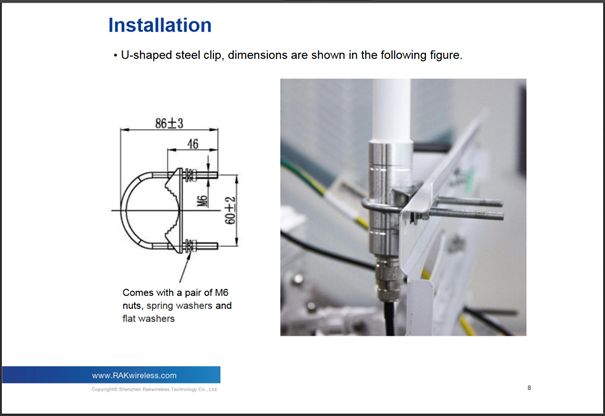
The disadvantage of this construction is that the stiffness with which the antenna is held up depends on the type of L-shaped rod. When the antenna is under windy conditions the vibrations of the antenna might result in metal fatigue. See Figure 1.
The advantage of this construction is that it is possible to install the antenna against a wall or mast. Disadvantage is that this will influence the radiation pattern and result in directivity away from the structure against which the antenna is installed.
Conclusion: The delivered clamps are usable but are not the best solution available. It is adviced to use clamps that allow installation on top of a pole.
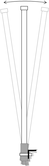
Figure 1: Viberation that might result in metal fatigue
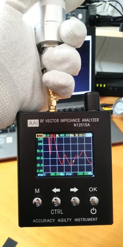
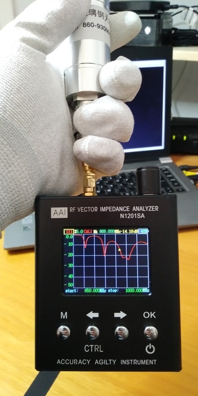
S11 measurements (return loss)
The antenna is specified to work from 860 to 930 MHz while delivering VSWR better than 1:2.0. This VSWR is equivalent to a return loss of -9,5 dB. The S11 parameters ware measured using a minivna tiny of mRs miniRadioSolutions. On the band edges of the antenna and on 896 and 915 MHz as these frequencies are of primary interest. The result is in the following table.
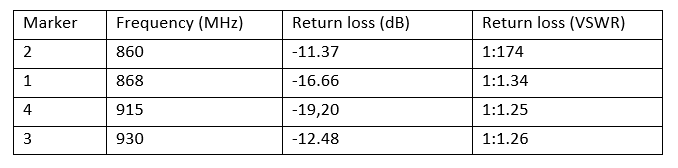
The figures below are the source of the previous table.
Conclusion: While professional antennas of Kathrein are specified at an VSWR of better than 1:1.5 (equals -13,9 dB return Loss) the RAK antenna performs better than this target value and can compete with the “professionals”.
When analysing the full band the RAK antenna does not meet the “professional” target but they are close.
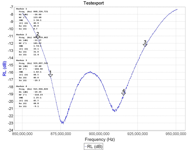
Figure 2: S-11 measurement (Returnloss) of Rak gen.2 antenna over specified band
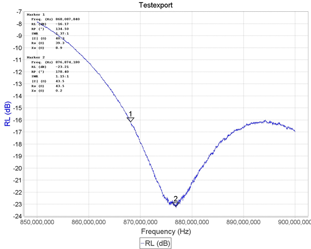
Figure 3: S-11 measurement (Returnloss) of Rak gen.2 antenna specific for 868 MHz
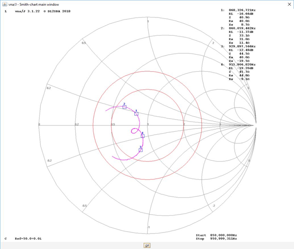
Figure 4: Smith-chart of Rak gen.2 antenna over specified band
Antenna gain
While I have no anechoic chamber nor a Open Air Test site (OAT) available I used the gateways of TTN-Apeldoorn and a reference antenna to compare the RAK beta antenna to. This results in a method know as the substitution method to determine the gain.
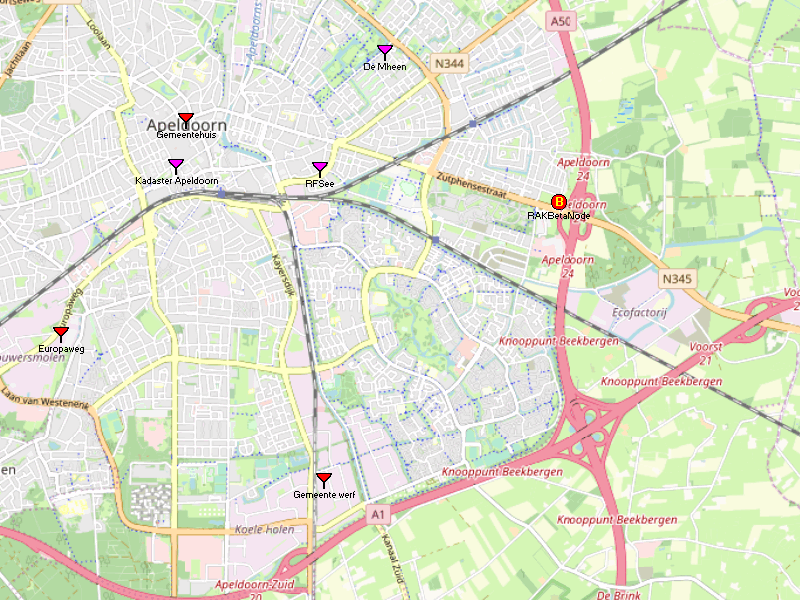
Gateways included in the test.
For data collection I used TTN Mapper app and a dedicated node.
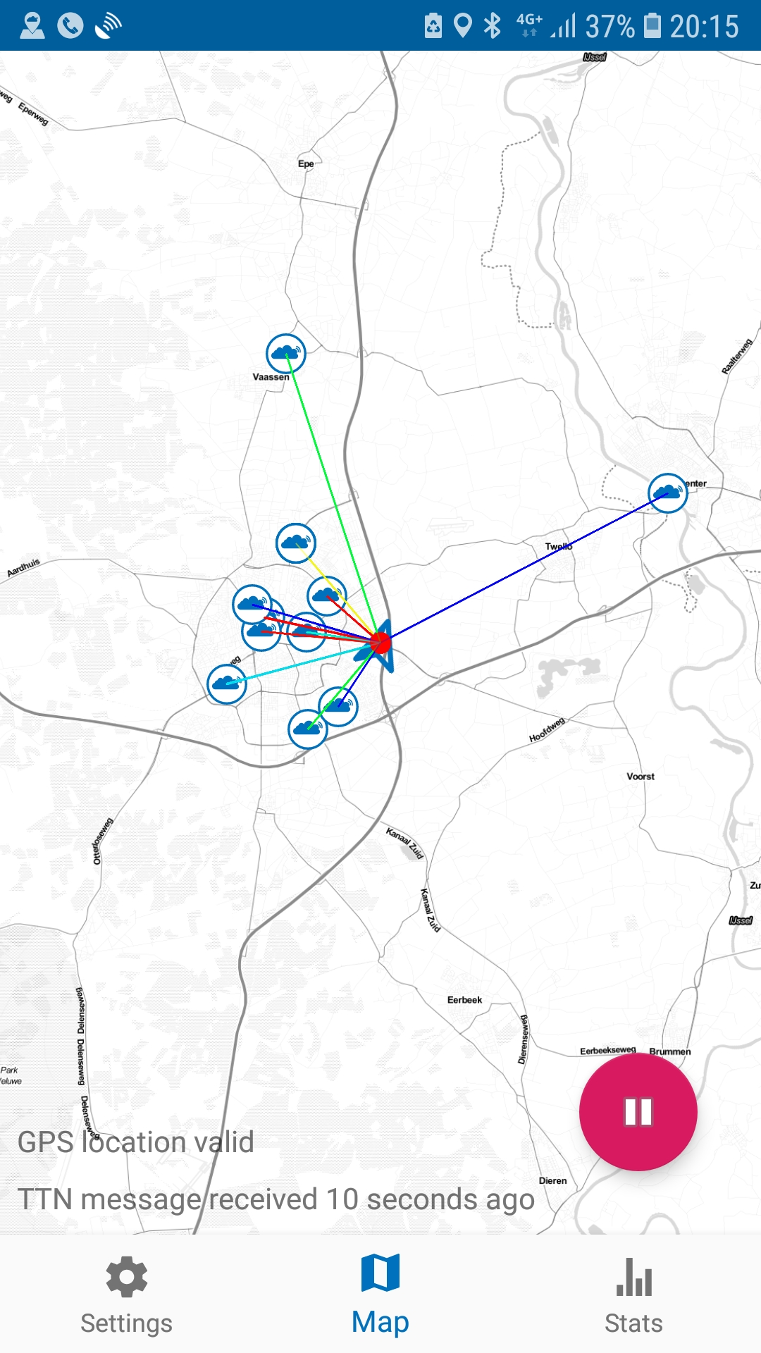
I two runs of approximately 15 minutes I collected around 100 measuring points over 6 gateway’s. The first run the RSSI was measured using the RAK beta antenna. The second run was measuring using the reference antenna.
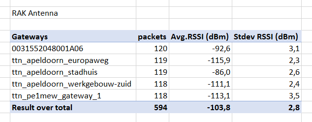
RAK antenna measuring
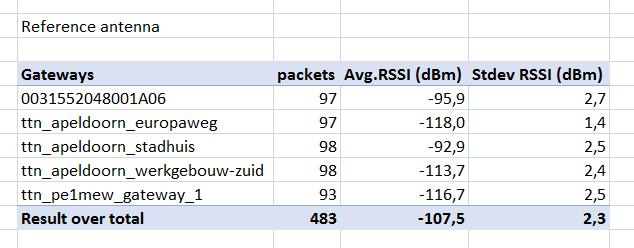
Reference antenna
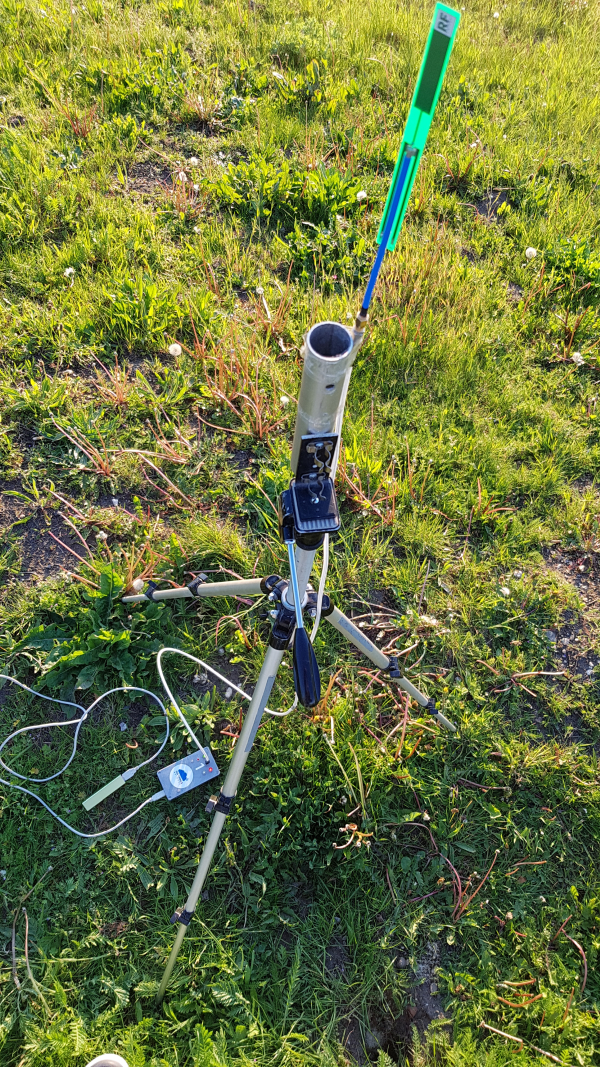
Test equipment, tripod with node
While studying the measurements it was found that one gateway had obstructed line of sight. This results in an anomaly and this data was discarded.
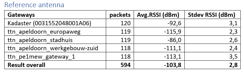
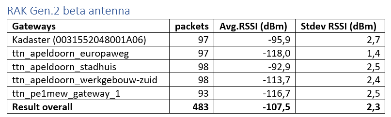
Both averages are subtracted and the result is the gain difference between the antennas. While the reference antenna is 0 dBd the gain is in dBd.
-103,8 – 107,5 = 3,7 dBd gain.
While the reference is 0 dBd this is 2,15 dBi.
2,15 + 3,7 = 5,9 dBi.
Conclusion: The gain specified by RAK is measured with this measurement.
Radiation Pattern
The radiation pattern is required to plan radio coverage using simulation tools like Radio Mobile. Therefore the radiation pattern is required in both H- and V-plane in a 1 degree resolution.
RAK only delivers data form a TRP measurement (3D) from which the required patterns can be extracted. The TRP pattern is at 30 degree intervals.
Conclusion: While competing manufacturers like Sirio provide the required radiation patterns RAK does not.
Overall conclusion
The new 6 dBi RAK antenna really delivers what is being promised. While the antenna mount is not a rigid solution it might work in many situations. It would be a welcome improvement when the clamps ware replaced by more mature ones that allow installation direct on the top of a pole. Th eproposed ones are shown below:
As I do simulate my gateways before installing I find the poor resolution of the radiation pattern a disadvantage. When RAK issued high resolution radiation patterns the can compete with the professionals.
Compared to many other antennas that have chinees origin the new RAK antenna has serious advantages. Serious value for money at low price.
16 Likes
Nice review.
What is the black paint you used on the base and on the enclosure?
The black stuff is anti corrosion paint.
1 Like
Hi All, It was brought to my attention by RAK that I accidentally reversed the labelling of the tables.
I verified this with the original data and provide hereby the correct labelled tables:
Cu, Remko
3 Likes
Hi All,
I have been testing the RAK 6 dBi antenna for around 3 weeks. The initial results were excellent with much impoved coverage and better than a 6db improvement over my old antenna. Over time the RSSI has increased as much as 30db. I has been very wet here in Melbourne Australia and I thought I may have had some water get into the SMA connectors or my co-ax. I checked very carefully for water and reinstalled everything including removing the antenna itself and it all came good again, no sign of water. Over the week the loss crept up again so I suspected the co-ax which I replaced last weekend. I replaced the co-ax entirely, no sign of water. This time l left the antenna in place. The RSSI impoved but is still 15db worse than when the antenna was first installed. I am beginning to suspect the antenna itself. When I originally installed the antenna I tested the SWR to around 1:1.4 at ~915Mhz all good. Any suggestions as to what next ? Is there any trick to mounting or setting up the antenna? It is mounted to a steel mast with the supplied U bolts. Any suggestions would be appreciated.
Regards
Chris Dann
Can jou replace the gateway to see if the degradation is caused by the receiver?
If it were mine, I would remove the antenna and cable to test how much power its actually radiating.
Its possible that the antenna SWR may report as normal, but that there are losses that restrict radiated power.