Every time I upload the example sketch LMIC-Arduino / ttn-otaa to the Lora32u4 V1.3 board, the connection on the USB port is lost after upload. Only after many attempts to upload a simple sketch such as Blynk (frequently press the reset button during upload) will “reset” the board and reconnect the port. Thereafter things went well until the next upload
I use the latest version of Arduino IDE and chose the Adafruit Feather 32u4 as a board. On this forum I have read several (old) messages about this problem, but no solution that works for me. The ttn-otaa example sketch does not use a sleep function so this cannot be the cause of this issue.
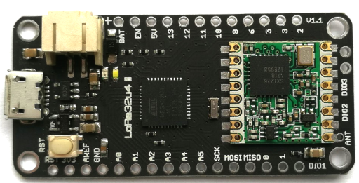
As suggested on several fora I have soldered a wirebridge between pin DIO1 and pin 6.
Is it better to throw this board away or does someone have a solution?
as Jac @kersing is a frequent visitor to the forum.
However as this was created before the LMIC library became a bit over-weight and the Arduino compiler added some code-bloat, it may well be that you did everything right but the code fills RAM, we get the stack hitting the heap and it all grinds to a halt.
Thanks for helping Nick! It seems that uploading succeeds after I press reset twice in quick succession shortly after compiling and immediately before uploading the sketch. After uploading, the connection to the port is often broken again, so it could very well be that this problem is caused as described by you. I will not throw the board away yet
Hold up on the Sloeber IDE - you’d be compiling the same code with pretty much the same result and you have to learn a new IDE which may add some complications.
The 32u4 has USB support built in to the chip - which is why it’s not got a CH340 and it works just fine - the original Arduino Uno uses it to provide the USB interface to the ATmega328.
Concentrate on the basics - does the module work (flash LED, read ADC, etc) without filling its brain to capacity with a LoRaWAN setup.
Just out of interest does what does the error say when you lose the port? I am getting similar issues with a Feather M0 on Windows. Also and I don’t know if this makes any difference as I think pin 6 is fine, but there are also suggestions for connection to pin 5 instead - don’t know if that is worth trying?
Generally you don’t get an error message - the whole device runs out of memory and locks up.
Changing which pin you connect to the RFM95 doesn’t matter as long as you change it in the software - which will crash very shortly after you download it unless you slim the code down.
The board disconnects from the USB port and Arduino IDE/Windows does not show any to connect with. So I can upload as described above but often the serial monitor cannot be used thereafter.
Seems like routine 32u4 behavior when the device has to go into sleep mode. For my projects using that controller, I add a 10sec delay in the setup. In this time, the USB is active. However once it goes into sleep mode or restarts after that, USB is not detected unless the board is reset.
Unfortunately, the 32u4 has much less program space than the 328. To if or not you are running out of memory, check what percentage, it shows you, is utilized after the sketch is uploaded.
Thanks all for helping! In my opinion the Lora32u4 board is not the best choice. It turned out it can be used when accepting above issues but there a better LoRa boards.
My solution for Windows 10 (based on this) needs to use both the base COM port and the Adafruit one. Pain in the neck but the only way I’ve been able to do it. Perhaps because of a "Device USB\[...] not migrated due to partial or ambiguous match." issue (Appendix 2) .
After boot, there needs to be a delay for Serial to start (e.g. delay(2500); Serial.begin();), otherwise the Adafruit Feather 32u4 port won’t initialize properly. See code sample in Appendix 1 below.
press the Reset button twice in quick succession. White LED will fade in & out cyclically. this is the upload mode. device seems to exit this after 14 seconds. so just press it again every 10 secs.
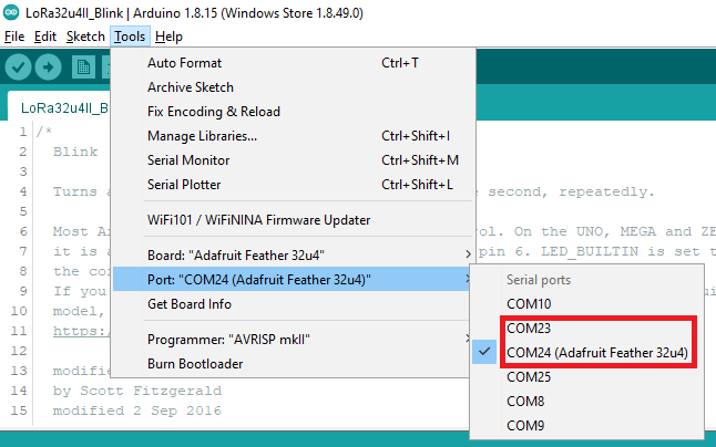
choose the basic COM port (for me, COM23)
press Ctrl+U to compile & upload
do step 1 periodically to keep the device in upload mode.
watch carefully when compilation hits the “linking” step. ensure that the device is in upload mode (do step 1).
after the upload is complete, change the COM port to the Feather 32u4 one (COM24 for me).
Open the serial monitor. The Serial object doesn’t seem to initialize until the Serial Monitor on your computer is opened. The code below compensates for that by using macros to replace Serial.print() and Serial.println().
Appendix 1.
Sample Blink code with serial printing.
/*
  Blink

  Turns an LED on for one second, then off for one second, repeatedly.

  Most Arduinos have an on-board LED you can control.

  modified further 11 June 2022 for Lora32u4

  original:
  https://www.arduino.cc/en/Tutorial/BuiltInExamples/Blink
*/

// the setup function runs once when you press reset or power the board
void setup() {
  // this is a simple way to do it, in which if the serial monitor on the PC isn't opened, the rest of the sketch won't run.
  //while(!Serial);

  // this is another simple way, but the sketch will run after 2.5 seconds, no matter what.
  //delay(2500);

  // now start Serial.
  //Serial.begin(115200);
  //Serial.println("started Serial");


  // initialize digital pin LED_BUILTIN as an output.
  pinMode(LED_BUILTIN, OUTPUT);
}

// 3. more useful way of using Serial with this device.
#define mySerialPrint(x) {if (serialStarted) Serial.print(x);}
#define mySerialPrintln(x) {if (serialStarted) Serial.println(x);}

int r = 0; // use to test whether `loop()` works even if the monitor is closed.
bool serialStarted = false; // use to ensure that `Serial.begin()` happens only once.

// the loop function runs over and over again forever
void loop() {
  if ((Serial) && (!serialStarted)) {
    Serial.begin(115200);
    serialStarted = true;
    Serial.println("Serial started");
  }

  r++;

  digitalWrite(LED_BUILTIN, HIGH);   // turn the LED on (HIGH is the voltage level)
  delay(200);                       // wait for a second
  digitalWrite(LED_BUILTIN, LOW);    // turn the LED off by making the voltage LOW
  delay(200);                       // wait for a second
  mySerialPrint("Hello ");
  mySerialPrintln(r);
}
Appendix 2.
Device not migrated event details:
Device USB\VID_239A&PID_800C&MI_00\6&28ce87a1&0&0000 was not migrated due to partial or ambiguous match.

Last Device Instance Id: USB\VID_05C6&PID_9091&MI_00\6&8576b09&0&0000
Class Guid: {4d36e978-e325-11ce-bfc1-08002be10318}
Location Path: PCIROOT(0)#PCI(1400)#USBROOT(0)#USB(2)#USBMI(0)
Migration Rank: 0xF000FFFFFFFF0022
Present: false
Status: 0xC0000719