My ttn node is still running, now below 2.0V DMM measured battery voltage. Button and motion as well as temperature still work. But Battery voltage reported has now changed from fixed 3280 to fixed 3286…
@HanspeterH
just think why your voltage is wrong, the reference voltage of ADC may be 2.5V (need to be checked) and thus all is below and wrong
You can try to swtich to 1.1V internal to read real VCC of Atmel, I already coded robust and accurate things like that here
https://www.thethingsnetwork.org/forum/t/full-arduino-mini-lorawan-and-1-3ua-sleep-mode/8059/32
but I’m not sure it will works on 32U4 code if for 328P
And the easier version
https://www.thethingsnetwork.org/forum/t/workshop-creating-a-ttn-node-labs-story-by-frank-beks/4491/16
Worth trying this if 32U4 support it and when battery goes below 3.3V regulated because before you always reading 3.3V with this method
@Charles Thanks for the hint.
After my node will have died tonight or tommorrow (some people tell me it should run until the battery voltage reaches 1.8V) I will probably try the code you mentioned in the BatteryMonitorLPP sketch…
Implemented getVcc() repo arduino-node-lib is up to date
  // This one is usefull when battery < 2.5V  below reference ADC 2.52V
  // because in this case reading are wrong, but you can use it
  // as soon as VCC < 3.3V,
  // when above 3.3V, since regulator fix 3.3V you should read 3300mV
  uint16_t vcc = node->getVcc();
  debugSerial.print(F("Vcc: "));
  debugSerial.print(vcc);
  debugSerial.println(F("mV"));
I also implemented on arduino-device-lib the other library a function to read VDD returned by LoRa Module in this PR
until merged, this lib version is here
Of course module need to be waked before 
  // Wake RN2483
  ttn.wake();

  uint16_t vrn = ttn.getVDD();
  debugSerial.print(F("VRN: "));
  debugSerial.print(vrn);
  debugSerial.println(F("mV"));
@Charles Ok thanks, I will try the LPP sketch next. A run down test will probably no longer be possible if it takes a few month as promised in the kickstarter…
…and the ttn node is still running the basic sketch and sending messages with measured battery voltage of 1.9V
The ttn node is still sending its messages but since 9 this morning also the temperature values are stuck at fixed 16 Celsius… i.e now the battery and the temp values are wrong. Motion sensor still detects motion. Measured battery voltage is now down to 1.8V and still sending. But the LED looks weak also, not bright any more.
@HanspeterH
amazing, sending at 1.8V
I’ve updated the sketch BatteryMonitorLPP to send 3 VDD reading (bat, RN2983 and VCC from ATMEL)
let’s see the most accurate
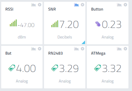
Button is button press duration, here 0.23s
1 Like
@Charles I want to add code to the batteryMonitorLPP to have the Vcc value in the message and not only in the serial Monitor. I added just one line below the vbat line:
// Just send battery voltage
lpp.reset();
lpp.addAnalogInput(4, vbat/1000.0);
lpp.addAnalogInput(9, vcc/1000.0); //not sure at all if correct…
Now with the 1.8V batteries from previous test with the basic sketch I get the following message data:
{ “analog_in_4”: 3.29, “analog_in_9”: 2.48 }
{ “analog_in_4”: 3.29, “analog_in_9”: 2.48 }
or in cayenne
Bat is incorrect for known reason but Vcc is also wrong … should say 1.8V But may be my line of code is totally wrong…
The last push send all the data needed on channel 4 (vbat TTN), 5 (vcc atmel with 1.1V reference voltage) and 6 (the value returned by LoRa Module)
  // Read battery voltage
  uint16_t vbat = node->getBattery();

  debugSerial.print(F("Bat:\t"));
  debugSerial.print(vbat);
  debugSerial.println(F("mV"));

  // This one is usefull when battery < 2.5V  below reference ADC 2.52V
  // because in this case reading are wrong, but you can use it
  // as soon as VCC < 3.3V,
  // when above 3.3V, since regulator fix 3.3V you should read 3300mV
  uint16_t vcc = node->getVcc();
  debugSerial.print(F("Vcc:\t"));
  debugSerial.print(vcc);
  debugSerial.println(F("mV"));

  uint16_t vrn = ttn.getVDD();
  debugSerial.print(F("VRN:\t"));
  debugSerial.print(vrn);
  debugSerial.println(F("mV"));

  // Just send battery voltage
  lpp.reset();
  lpp.addAnalogInput(4, vbat/1000.0);
  lpp.addAnalogInput(5, vcc/1000.0);
  lpp.addAnalogInput(6, vrn/1000.0);
your code looks good, that is strange, what value is returned by Lora module ?
hmm sorry, I dont understand Lora module… where could I see this value?
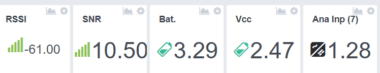
@Charles I am now running your latest code with low batteries:1.8V. Results
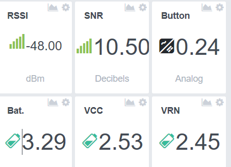
messages log:
{“analog_in_4”:3.29,“analog_in_5”:2.48,“analog_in_6”:2.4}
{“analog_in_4”:3.29,“analog_in_5”:2.53,“analog_in_6”:2.45,“analog_in_7”:0.24}
{“analog_in_4”:3.29,“analog_in_5”:2.48,“analog_in_6”:2.41}
{“analog_in_4”:3.29,“analog_in_5”:2.54,“analog_in_6”:2.46}
{“analog_in_4”:3.29,“analog_in_5”:2.53,“analog_in_6”:2.45}
{“analog_in_4”:3.29,“analog_in_5”:2.52,“analog_in_6”:2.45,“analog_in_7”:0.27}
{“analog_in_4”:3.29,“analog_in_5”:2.47,“analog_in_6”:2.4}
humm, that’s really interesting, 2 methods to read voltage on 2 different chips, both have same results, could be interesting to add a delay between reading instead of reading after wake
would you try to add a delay(5000), just before the 1st reading just curious.
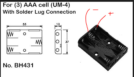
1.8v between these points ??
I think you measured only 2 batteries in series, not all 3
@BoRRoZ
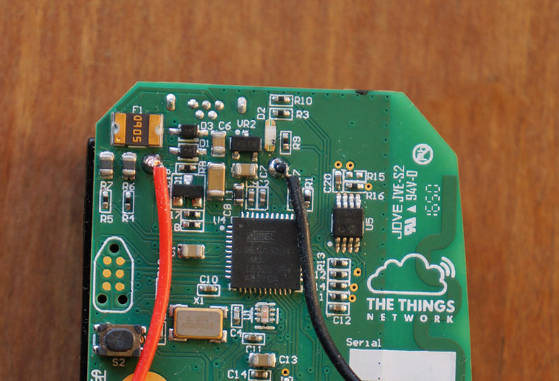
Nice picture, do we have the gerber files so see wiring?
looking at this picture, it could be interesting to cut wire of UVcc (pin2) before via and connect uvcc pad to VUSB as seen above, if it works we could have best low power node 
@BoRRoZ I think he’s got 3 but really low !!
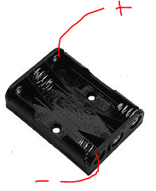
Ohhhh correct @BoRRoZ lost my time because battery connector not classic wired lol
May be that’s the trick !!
yes… if you meassure from the top you make easy a mistake
First time I powered with my power supply like that
my power went in protection (short circuit ?), it drove me mad
@Charles, the schematic and layout is in Altium format available. On my PC I found “Altium Designer Summer 09 Viewer” to view it, this was free, but I think now it’s not available anymore.
I did exactly what you suggested and this works perfect. I have low power and can still program, without doing any jumper things…
What thing? wire cut uvcc? If so would you mind post a picture of this awesome fix?
Exactly, wire cut +UVcc. Sure: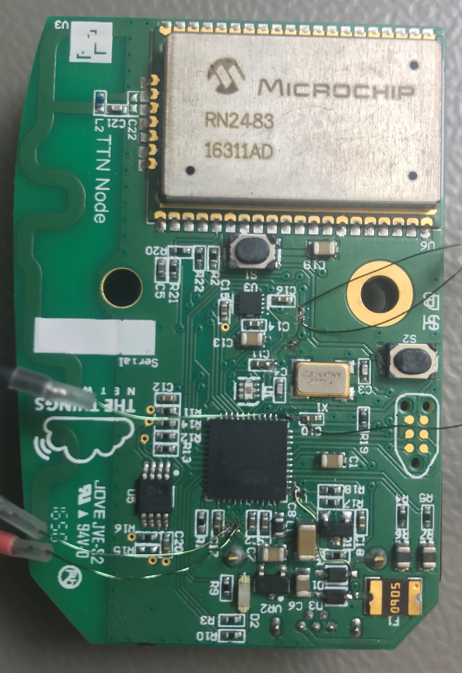
All the wires are only to measure the current of the different modules (uC, RN2483)
It’s the wire in the right lower corner. Which goes to D3.