maybe you can see it here better:
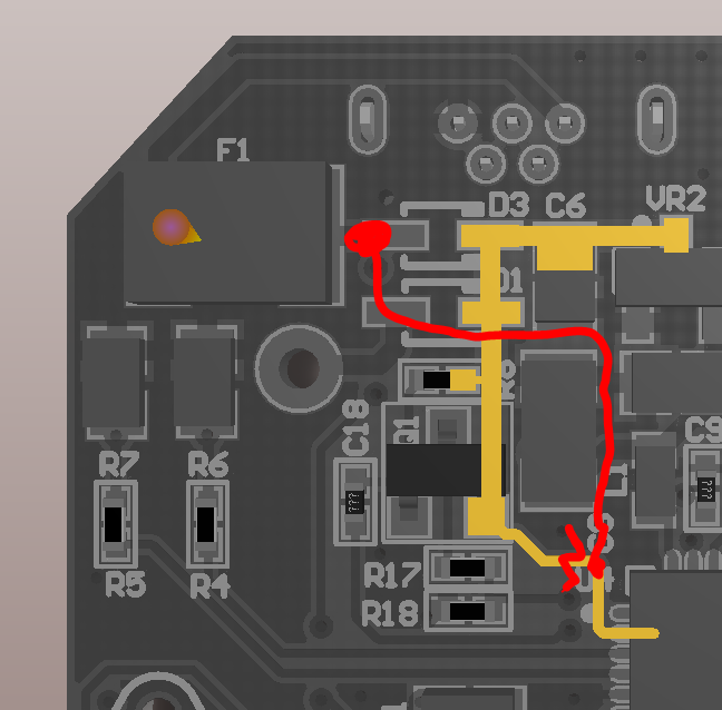
it’s a bit tricky to do it without a microscope.
1 Like
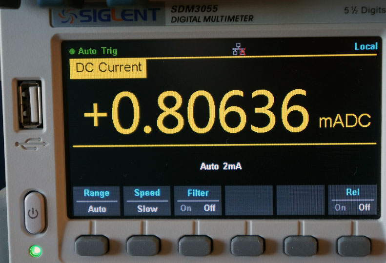
Indeed, you are right. I took the batteries out and measured them in arow… and guess: 2.9V
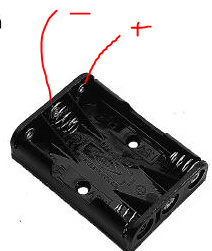
measure according to picture = 2.9V
The vbat value is stuck as the voltage is below 3.3V, the VCC and VRN values are below the actual battery voltage when connected only to the DMM but are probably the voltage the chips see after some loss of other components before the chips…maybe. Would have to look at the chematics of the ttn node. But anyway we have now a readout which works below 3.3V
{“analog_in_4”:3.29,“analog_in_5”:2.52,“analog_in_6”:2.45}
{“analog_in_4”:3.29,“analog_in_5”:2.52,“analog_in_6”:2.44}
{“analog_in_4”:3.29,“analog_in_5”:2.52,“analog_in_6”:2.44}
{“analog_in_4”:3.29,“analog_in_5”:2.51,“analog_in_6”:2.44}
{“analog_in_4”:3.29,“analog_in_5”:2.51,“analog_in_6”:2.44}
{“analog_in_4”:3.29,“analog_in_5”:2.51,“analog_in_6”:2.44}
{“analog_in_4”:3.29,“analog_in_5”:2.51,“analog_in_6”:2.44}
{“analog_in_4”:3.29,“analog_in_5”:2.51,“analog_in_6”:2.43}
{“analog_in_4”:3.29,“analog_in_5”:2.51,“analog_in_6”:2.43}
{“analog_in_4”:3.29,“analog_in_5”:2.51,“analog_in_6”:2.43}
{“analog_in_4”:3.29,“analog_in_5”:2.5,“analog_in_6”:2.43}
{“analog_in_4”:3.29,“analog_in_5”:2.5,“analog_in_6”:2.43}
{“analog_in_4”:3.29,“analog_in_5”:2.5,“analog_in_6”:2.43}
{“analog_in_4”:3.29,“analog_in_5”:2.5,“analog_in_6”:2.43}
{“analog_in_4”:3.29,“analog_in_5”:2.5,“analog_in_6”:2.43}
{“analog_in_4”:3.29,“analog_in_5”:2.5,“analog_in_6”:2.42}
{“analog_in_4”:3.29,“analog_in_5”:2.5,“analog_in_6”:2.42}
{“analog_in_4”:3.29,“analog_in_5”:2.5,“analog_in_6”:2.42}
{“analog_in_4”:3.29,“analog_in_5”:2.5,“analog_in_6”:2.42}
Anybody measured the uA already the node uses in sleep mode? Or uA/mA averaged over some days or has estimated how long the ttn node will run with all sensors enabled?
1 Like
that is by design ![]()
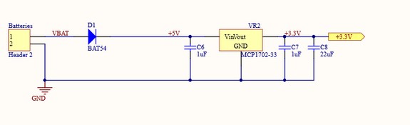
Vbat is meassured after the MCP1702-33 voltage regulator… the output wil be 3V3 (thats what the processor gets to eat) when the input (the 3 batteries in series) will be between 2v7 and 13v
@HanspeterH
@BoRRoZ is correct, 2.9V in, remove vdiode and vreg and you get 2.45v out, makes sense
@Charles we can’t expect everyone to cut traces and solder wires, best is to concentrate on a basic software solution (library update) like you already did.
- that new BatteryLPP… is that now the lowest power software solution ?
@BoRRoZ I totally agree, but I would like to know why the datasheet implementation has not been followed, may be an obvious reason.
Anyway, I think since it’s just a PCB routing change it could be (should) implemented on future batches without any issues, @johan, @laurens, @wienkegiezeman do you think it’s possible to take this into account?
This change just bring low power sleep consumption from 300uA to 40uA, approx 10 times less, just by changing a trace.Change definitively worth it.
@BoRRoZ, yes at least the less consumption sketch since no more watchdog to wake us every 8 seconds to do nothing 
ok I start to test … the network status is also back to normal ![]()
- agree if a little pcb routing is neccessary it must be done in for future batches
excellent, if it’s working fine also for you I’ll create the Pull Request so it’s merged into official lib
1 Like
My ttn node running the batteryMonitorLPP sketch stopped sending messages at measured battery voltage (all 3 this time…) of 2.65V. Also the latest messages before death had strange button values… I never pressed the button for 15 seconds… VCC says 2.3V
{“analog_in_4”:3.29,“analog_in_5”:2.42,“analog_in_6”:2.34}
{“analog_in_4”:3.29,“analog_in_5”:2.42,“analog_in_6”:2.34}
{“analog_in_4”:3.29,“analog_in_5”:2.41,“analog_in_6”:2.34,“analog_in_7”:0.26}
{“analog_in_4”:3.3,“analog_in_5”:2.33,“analog_in_6”:2.27}
{“analog_in_4”:3.3,“analog_in_5”:2.33,“analog_in_6”:2.26,“analog_in_7”:15.33}
{“analog_in_4”:3.3,“analog_in_5”:2.3,“analog_in_6”:2.23}
{“analog_in_4”:3.3,“analog_in_5”:2.3,“analog_in_6”:2.23}
Time to cut a wire and solder an additional one…
I agree. With the new SW it may run a few month. Quite ok for a training device. However I want to train for real sensors with a battery lifetime of a few years for example for my earthquake sensor.
build it yourself… this forum is full with examples
for training and programming at home, for education purposes the TTN node is perfect with its onboard sensors. and included enclosure/battery compartment.
plug and play
Thanks for the tip but actually I am running my own built sensors and a gateway since almost two years thanks to ibm’s lmic and the early availability of the Things Network. But I still have to learn about the deep sleep implementations on Arduino based boards.
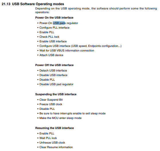
The datasheet of the 32u4 states that is is possible to disable the regulator in software. I am unable to test it at the moment, but setting the clearing the UVREGE bit in the UHWCON register detaches the regulator from the pin. The code would be:
UHWCON &= 0xFE;
See figure 21-1 from the complete Atmega32u4 datasheet. This will disable the usb section, so I recommend to implement it in the deepsleep() method in the Things Node arduino library. The deepsleep method is only called if no usb cable is attached. When waking up the regulator can be enabled again with: UHWCON |= 0x01;
@MysteryGuest
thank’s a Iot, I searched for that in datasheet, but searched for UVCC, should have search for USB Pad or USBVreg 
I pushed the changes, @BoRRoZ, may be you can let us see what your scope measure?
I’m not sure it will be able to get back USB correctly because we mixed sleep/power on/off USB Mode and according the datasheet we should do other way
but let us see if we win some consumption with this quick fix
1 Like
OK Charles thanks.
I removed the previous adapted TTN node lib and downloaded the zip file from your github (didn’t know if TTN pushed it also)
installed the library through the arduino IDE and downloaded example CayenneLPP, that’s the demo example with all sensors on.
It compiled and I uploaded it to the things node and it worked perfect.
sleepconsumption with all sensors on is now :
only thing, when compiling I get this error (it worked so thats no problem but I don’t understand the message)
D:_TTN node LPP\CayenneLPP2\CayenneLPP2.ino: In function ‘void setup()’:
D:_TTN node LPP\CayenneLPP2\CayenneLPP2.ino:37:20: warning: invalid conversion from ‘void ()()’ to 'void ()(uint8_t) {aka void (*)(unsigned char)}’ [-fpermissive]
_ node->onWake(wake);_
_ ^_
In file included from D:_TTN node LPP\CayenneLPP2\CayenneLPP2.ino:1:0:
D:\0 - ARDUINO sketch\libraries\arduino-node-lib-master\src/TheThingsNode.h:135:8: note: initializing argument 1 of ‘void TheThingsNode::onWake(void (*)(uint8_t))’
_ void onWake(void (*callback)(uint8_t wakeStatus));_
_ ^_
Sketch uses 27246 bytes (95%) of program storage space. Maximum is 28672 bytes.
end conclusion : this library works and uses 15 times less then original TTN one so that’s a big plus , goes to sleep and wakes up and with some tweaking there is maybe even more possible in the future.
tnx Charles !
- now I’m thinking
this can be done for the TTN UNO lib to ?
1 Like
I did the same and got exactly the same errors as @BoRRoZ
… and digital input 3 (isMoving) never gets a high value. Have not looked at the code yet.
serial monitor always shows Moving: No
… and also i am not sure if this sketch is a good example with a payload size of 42 bytes sending every minute.
1 Like
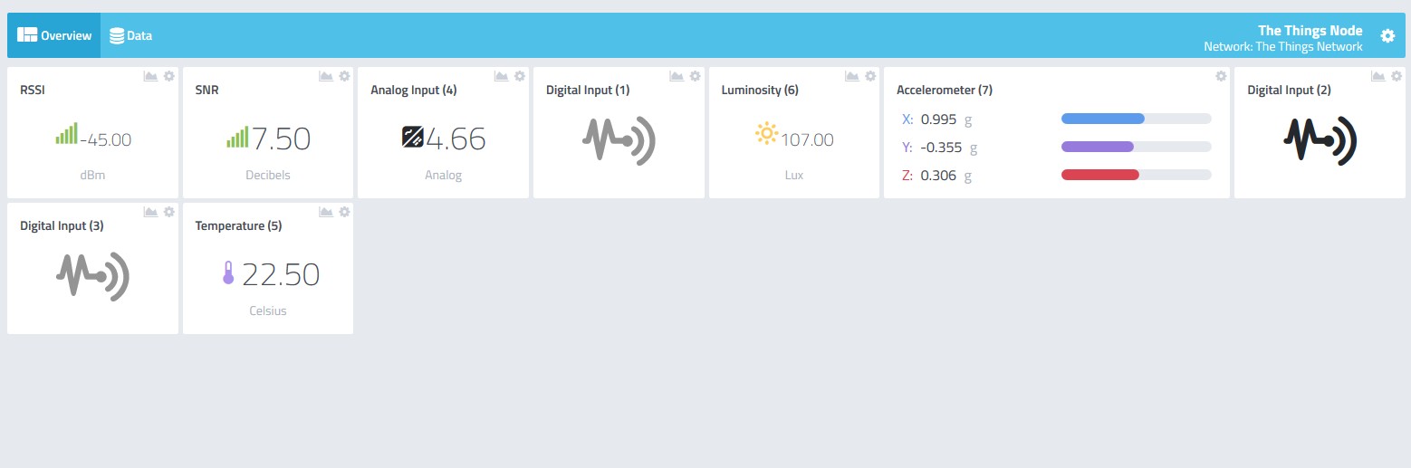
seems to me that every sensor is working
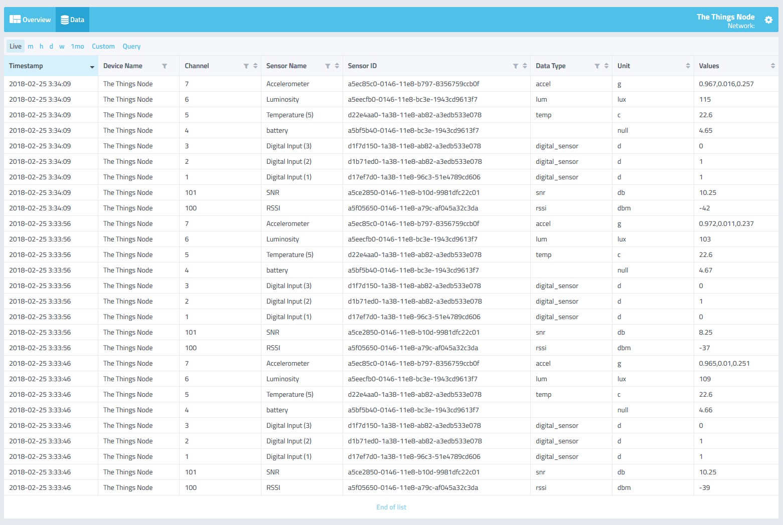
nice new Cayenne function : live data
- maybe you’re right about sensor 3… have a closer look

My ttn node running the newest cayenne lpp sketch from @Charles has started to behave strange. When I press the button the blue light is on for 33 seconds, The battery voltage measured is 3.8V, vbat is 3.34V.
It is running on batteries. Msg data:
accelerometer_7.x:-.008accelerometer_7.y:0.006accelerometer_7.z:1.023analog_in_4:3.34digital_in_1:1digital_in_2:0digital_in_3:0luminosity_6:1temperature_5:22.9
When running on usb power it behaves different also: stays permanently with green led on until button pressed or acceleration detected, then led is blue for 3 seconds and then steady geen again, never goes black. Really strange, it did not behave this way a few hours ago. No download of another sketch took place. Also temperature readouts are wrong, went higher and higher now steady on 26 degrees instead of 22 degrees
Drives me nuts: Now it is behaving normal again and temp is ok again…I did not change anything.
where do you watch that data… Cayenne or the TTN console ?
when the LED stay green its a sign there’s no gateway connection…
@HanspeterH
Saw the same behaviour today, I need to check, but kind of complicated, since may be it’s related to usb reg power off and on with sleep mode and I would like to have a real serial for debug, AltSoftSerial works on pin that is connected to ACC INT so I can’t use it also.
I think may be at end os setup
on BatteryMonitorLPP.ino, when starting, magenta led means joining, just after that red=not joined, green= joined.
I just pushed CayenneLPP.ino sketch to have same behaviour