The WORKBENCH part 3

Less than €2.45 actually (per 4).

https://www.aliexpress.com/item/32807045241.html

Are not 700 mAh but more like 550 mAh
See test at lygte.dk

“With protection” but no discharge low voltage cutoff protection.

@borroz Ah, you were first. :grinning:
I bought a set there.

:rofl:

No winning, no word games but facts and real life LiFePO4 14500 endurance tests with my ESP8266 weather nodes. Lasts 1+ month on a charge. Measuring temperature, humidity, barometric pressure and light intensity (3 sensors) and sending updates via MQTT over WiFi every 10 minutes.
When I do not monitor/check low batt messages every day its easy that a battery gets drained below 2.0V (down to 0V) for more than a day. Not good for the batteries.
When at 0V the charger does not accept them as LiFePO4 (then need to revive them by CC charging with lab power supply for a while until they contain some charge again, after which the charger will accept them again).
After battery reached 3.07 V the node worked for another 3 days, down to 2.34 V.

Was a known fact when I ordered (see test at lygte.dk).

They at least somewhat approach rated capacity, and more important these can be re-charged. :stuck_out_tongue_winking_eye:

I searched for other solutions to implement a low voltage discharge protection for single LiFePO4 cells and came across this solution (which combines it with reverse battery polarity protection).

With following diagram:

e6Azj%5B1%5D
Note: M3 is a P-channel MOSFET but (incorrectly) drawn as N-channel.

The reverse battery protection (top right MOSFET) uses almost no current, but the low voltage discharge protection constantly draws up to 20 uA (R2,R3). The battery protection boards mentioned earlier use much less: max 5 uA (if their advertised specs are correct).

20190601_104435

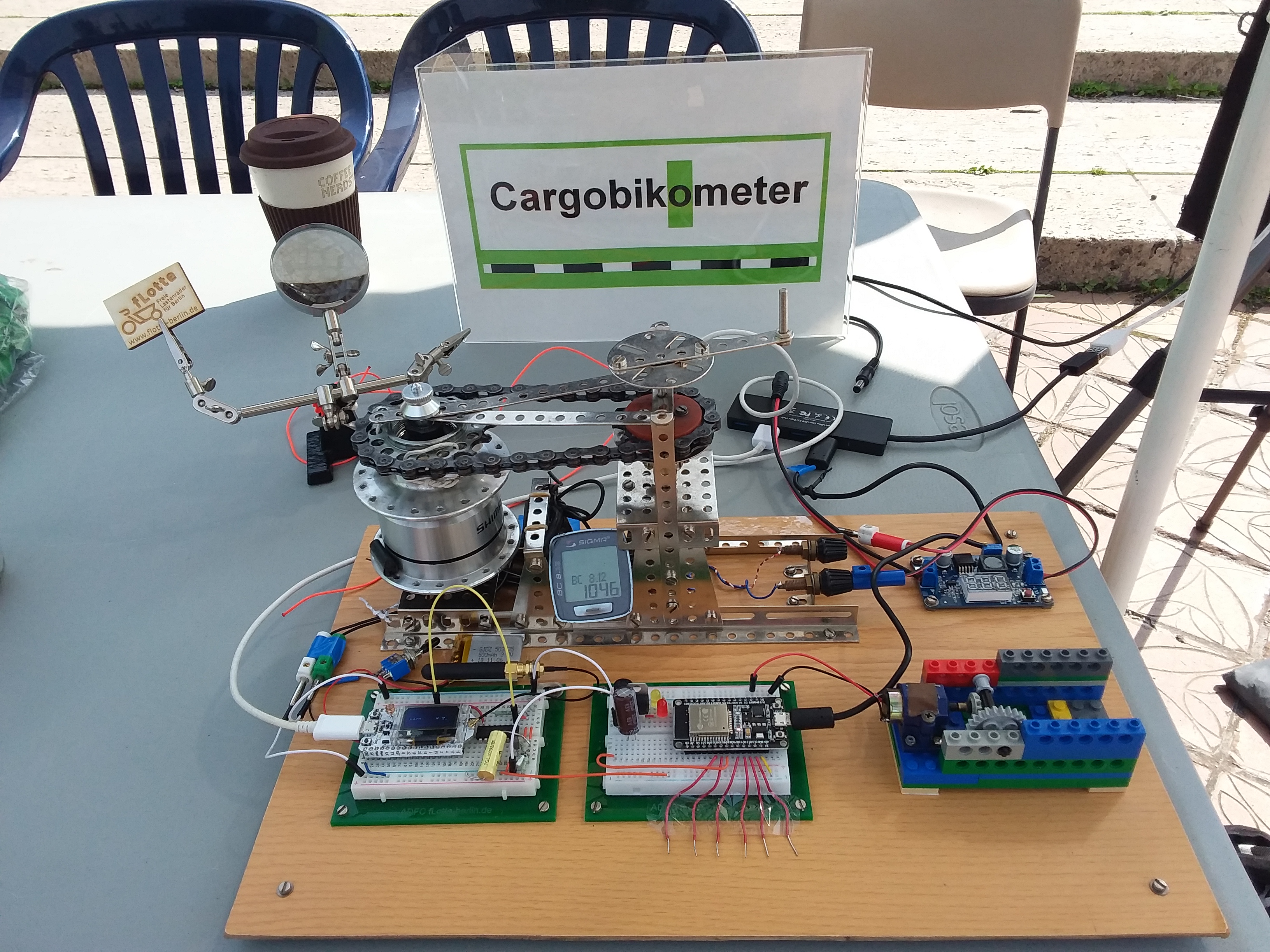
This is my Cargobikometer demo solution for the ADFC Berlin fLotte project, which is currently under development. The hub dynamo can be driven by hand or by a DC motor. The signal from the hub dynamo will be converted from a sine wave into a rectangle signal by a schmitt trigger. To avoid an always running hub dynamo during programming, I use a simple ESP32 based signal generator with touch sensors for switching the frequency. For fun I drive a little motor from the hub dynamo voltage with an AC-DC converter.

The program for counting the distance works very well, but now I have to transmit the distance value via LoRaWAN. The program for sending a fixed distance value via TTN http integration works also very well, but if I put both parts together, the pulseIn function returns always zero.
I already posted the code examples 2 days ago in the forum.

It would be nice, if somebody can help me to fix the problem. When the problem is fixed, I can move to the next step in my project, finding a suitable battery backed hardware device and a waterproof case, which should be placed on the bottom side of the cargobike.

1 Like

Hi,

you have the complete sketch somewhere (github ?)

I think that the dynamo measurement can’t be interupted for LMIC So my first idea would be to
use A - a non LMIC node or B - an interface between the dynamo and the node, maybe small pre processor ATtiny 85 / I2c

Hi,

code is available here: https://github.com/fLottes-adlershof/cargobikometer

1 Like

Your frequency measurement stuff looks quite complicated. Instead of blocking to measure on and off time, you actually only need to count cycles by detecting the rising edge.

I would setup an edge triggered interrupt to increment a counter. Read that value every second and you have your frequency.

You can definitely do this and run LMIC on the same chip.

1 Like

OK I’ve printed it and its clear that you later decided to ‘hack’ LoRaWAN to the original code and that gives (timing) some problems.
Have a look into this (later), I understand what @cjhdev mentioned, but that requires a complete rewrite of all the code.

testdev

looking forward to make this work…
would be nice to create a ttnmap compatible device first, to visualize the workings.

strange thing atm: not allowed to create abp join…

I read comments in the web some months ago, that frequency measurement works better for low frequency signals (1 to 100 Hz) by measure the period of the signal. Therefore I switched from interrupt based measurement to the current mechanism.

The part I dislike most about making prototype PCBs from scratch is flashing the bootloader. So I made this device to make that task simple and stress-free.

1 2
This can be used to flash a bootloader on to 32Pin Atmel MCUs like the ATMEGA 88/168/328 before placing the chip on a PCB. Saves assembly time.

Design files are available as referenced here

The design can easily be modified for 44Pin ATMEL Chips like the ATMEGA32u4.

4 Likes

very cool ! :sunglasses:

I can’t help you with PYCOM things… maybe some other TTN’ers.
There’ss a forum but I’m sure you’ve searched and asked there too

I have a few LoPy and FiPy boards and the Pycom ABP example has always worked out of the box.
Are you having an inssue connecting a programmed device to TTN or defining the application/device as ABP on your TTN control panel?

Sounds a bit odd in any case?

G

1 Like

Hi @Lichtschilder, I read your other post that the TTN web console won’t let you set the device to ABP.

I use a fair number of Pycom Lopy4 systems in EU and have no problem using them in both OTAA and ABP on TTN.

For configuring a device to use ABP I follow these steps:

Make sure that I am the application owner or a collaborator with permission to view and edit devices.

Register the device using the normal TTN console; Dev ID, Dev EUI, let the system generate the app key.

Then exit to the applications list of devices and select the new device.

Then select settings and then select ABP and the console will change to ABP settings and will generate the keys and DevAddr.

If this fails then I suggest that you try from fresh on a newly registered application.

1 Like

hi Tim,

thanks for the response, the web interface allowed me to change if needed.

do you have any experience creating a TTNmapper using lopy and pytrack?

hope to find a working method

Hi @Lichtschilder, the project that I’m working on has done a lot of “walk-testing” but we have not used TTNmapper as we need to keep our own records and integrate with our RF coverage planning tools and Google Earth.

We use Lopy4 + Pytrack units and walk routes sending an uplink every 2 mins and locally record the uplink no., GPS co-ordinates, etc. on the Lopy4 storage. Then we merge with a record of the uplinks received on TTN and produce standard GPX files that can be viewed on Google Earth along with the predicted RF coverage in KMZ files.

An example walk through a predicted coverage gap in between three gateways about 10km apart in hilly country is shown below. The green waypoints show successful uplinks. The numbers are the uplink number and the count of gateways that received the uplink.

Development of this system on Lopy4 took about 3 days.

20190228-JB--PL-walk-test-01

2 Likes

that sounds like a nice project :slight_smile,
could you share some of the lopy code?