The WORKBENCH part 5

Here is something that should be on your workbench: https://nl.aliexpress.com/item/32876049554.html?spm=a2g0s.12269583.0.0.4d4425a6RHIncR

afbeelding

2 Likes

Seeed seems about to release a new LoRaWAN module:

LoRa-E5 STM32WLE5JC Module, embedded SX126X and MCU for LoRaWAN Wireless Sensor Network & IoT devices - EU868 & US915

2 Likes

I just had one. Ordered on the 11th, arrived in the UK on the 16th.

The useful mod I saw on You Tube is to add a switch to turn off just the heater elements, so you can still keep an eye on the plate temperature.

I can bin my electric frying pan at last.

2 Likes

I have had a chance to try the hotplate.

I have been working on a ESP32 based PCB that can take a choice of SX126X, SX127X or SX128X LoRa modules. I have versions of the board for Pro Minis, but that does mean they lack in program space.

I first used the hotplate to remove an ESP32 from a previous PCB. Once I had worked out the right temperature setting to use it was very easy to heat the old board and remove the ESP32. If I had heated the board from above with a blower, there would have been the risk of maybe unsoldering all the bits inside the ESP32.

I soldered the ESP32 in place by hand on the new board but when powered up there was a fault. Eventually it seemed to be a short between the ESP32s GND and VCC pads. So I used the hotplate to lift the ESP32 and found and corrected the solder bridge. I placed the ESP32 over the pads again, let the hotplate heatup and the ESP32 neatly soldered itself back in place. No heat damage to the PCB at all. Overall a very easy operation.

The temperature indicated was maybe 25C out from what the setting was, so perhaps you might not want to use this hot plate for making commercial stuff, but for the DIYer it is well worth the money.

The board by the way has a power supply that survives the WiFi switch on current pulse and has a deep sleep current of 20uA. There is a FRAM and a micro SD card holder on the back. Even the LoRa modules work.

Easy_ESP32_Complete

Easy_ESP32_Detail

2 Likes

Connecting LoRa devices to 5V Arduinos.

I am sure that observant LoRaites will have noticed that for the SX127X LoRa devices the data sheets have no maximum voltages stated for the logic pins, SCK, MOSI, NSS etc. This is very odd from Semtech, are users of the devices supposed to guess ? So what does the lack of information mean, that the pins are 5V tolerant possibly or that it does not matter and you could put many kilovolts on a pin with no risk to the device ?

We all may assume these LoRa devices are 3.3V logic devices but some who try it say they do work (for a while at least) when hooked up to a 5V Arduino such as a UNO.

So I checked what happens when I connected a SX1276 LoRa module to an Arduino UNO (do this at your own risk). The device appears to work, you can read and write to registers etc. However the LoRa device is putting out signals of around 4.2V peak on the MISO pin.

This is odd I thought, the device is only connected to a 3.3V supply ?

Turns out the LoRa device is being phantom powered by the 5V outputs of the UNO, NSS and MOSI and this raises the LoRa devices VCC supply to around 4.1V.

Oh dear … the absolute max voltage on the VCC supply pin is 3.9V and the operating range is listed as 3.7V max.

So thats why you should not connect 3.3V LoRa devices directly to 5V Arduinos.

5 Likes

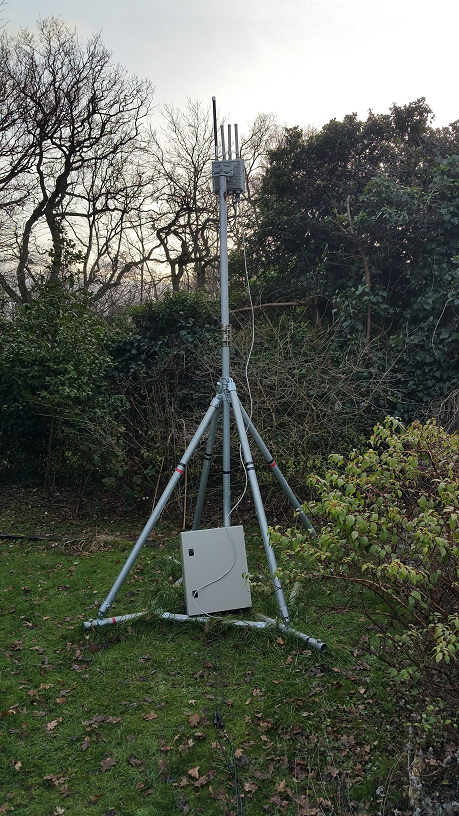
A potential client interested in deploying one of these:
image

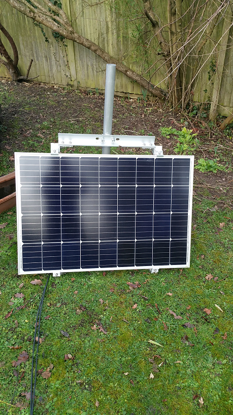
powered by one of these:
image

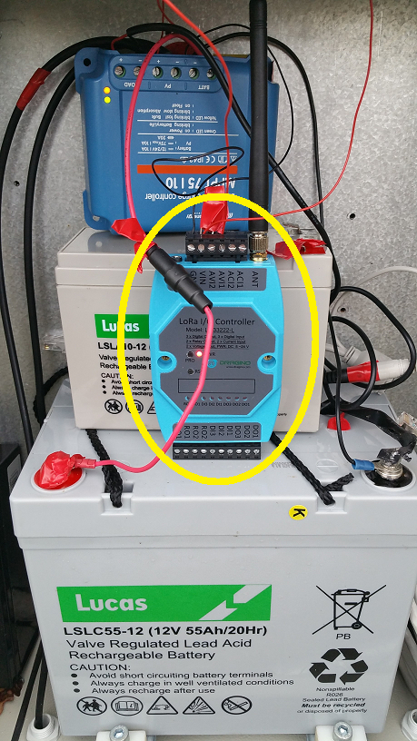
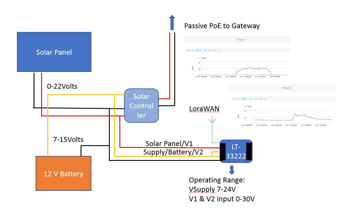
Wanted an easy way to monitor the battery voltage. Problem was I didnt have a lot of free time to build a low cost node lash up and I also decided it would be useful to report the solar panel output voltage. Then I remembered I has a Dragino LT-33222 from our friend @edwin and the team. Perfect - supports 2 analogue input voltages for monitoring (0-30V) as well as running off a supply upto 24V, thereby allowing a direct connection to relevant circuit points without any adaptation or changes. A bit more expensive than a self build perhaps but time is money and a better value proposition at the time. Also ( :thinking: ) it has a number of Digital I/O and relay contacts so next step is to consider how these might be used for battery & load switching/failover automation, etc…

Lash up circuit with output taken directly from TTN Integration to Cayenne dashboard (for easy sharing with the client)
image

Installed and happily running for a couple of weeks now as part of the system POC
image

8 Likes

For anyone itching to play with one since last weeks TTConf:

1 Like

Prototyping - now I know what the longer breadboards are for …

Big-mess-o-wires

1 Like

Raspberry Pi Pico, DS18B20 on 1-Wire library from the original code so not production ready, RAK4260 module.

Pico_DS18B20_LoRaWAN

The Pico in the foreground is a Pico setup as a programmer / debugger.

Still working on the exact figures but the Pico isn’t going to be suitable as a battery device as the minimum I’ve seen so far is 900uA. As such I won’t be stampeding to use these unless I end up the a compelling use case - probably edge-AI/ML.

2 Likes

Take a couple of RPi Pico boards, a hand full of of LoRaWAN modules (Note not LoRa modules, so you dont have to worry about porting e.g. Aunties version of LMIC or other such LoRaWAN stacks! and avoid wrangling Arduino-like implementations for such), add a few sensors… and a nice weekend project?! If LoRaWAN Stack based devices should go straight to V3? :thinking: what can possibly go wrong?!

image

1 Like

@Jeff-UK, this may help: GitHub - HeadBoffin/Pico-Three-Way-Serial: Serial communications example/starter for the Raspberry Pi Pico board

1 Like

Perfect thanks, from the Github : the application is for a comms module on a UART like ESP8266 for Wifi or a LoRa/LoRaWAN AT based module and have a GPS on another UART : Just what I need :slight_smile:

p.s. took nearly a month but finally got the picture to load and completed the post! (Remembered that one and couple of other pics had been interupted during phone download - looks like however it was corrupted stopped forum loading - 2nd pull from phone worked fine :wink: )

:thinking: Would be interesting to hear here if other Forumites have a Pico working with LoRaWAN/TTN…come on guys get posting! :slight_smile:

1 Like

Made a programmer/debugger/serial/power cable loom for my Generic Node Sensor Edition:

GenericNodeSensorEdition

The double lead from the USB-Serial adapter allows for monitoring the serial feed without having to plug in / power the ST-Link.

5 Likes

TinyThing4200 = ProMini with RAK4200 to off-load the LoRaWAN element, leaving plenty of space for sensors and extended firmware but still accessible for those that don’t code ARM all day every day.TinyThing4200_RAK

TinyThing4200_ProMin

1 Like

MiniPrototyping4200 = ProMini, RAK4200 and a surfeit of connectors. Pile of these about to go out with a variety of sensors to do some getting started training via remote.

MiniPrototyping4200

There will be a TTIG in the box for their local gateway.

2 Likes

Here is my version. It does not provide power but has the advantage that it requires only one USB port (because the STLink-V3MINI supports this).

The small adapter board is not standard included with STLINK-V3MINI but comes provided when ordering from Waveshare.

3 Likes

Today I investigated the performance of the Aurel GP 868 antenna that can be purchased at Conrad (Aurel GP 868 Ground Plane Antenne Antenne | Conrad.nl).

This antenna is nice looking with rubber protection at the ends of the radials

before After

From experience, I know that these rubbers will detune the antenna frequency down, and when I verified the antenna I found that the 868 MHz antenna actually was resonant at 816 MHz and not 868 MHz. At the resonant frequency, antenna performance is pretty good with 18 dB return loss. However, at 868 MHz return loss was 9 dB. That did not meet my quality standards.

afbeelding

Because the antenna resonance frequency was lower than 868 MHz the elements of the antenna were too long and can be shortened to tune for an exact 868 MHz. In an iterative process with intermediate measurements, I shortened the elements on average 2 mm with a satisfying result: return loss was >26 dB from 864 to 873 MHz.

afbeelding

Radio link performance is directly influenced by the quality of the antenna. I know this antenna is performing well.

The only problem left is that the antenna is not waterproof but that can be solved with some Self-amalgamating tape.

7 Likes

Is the 2mm for use with the rubbers or without them?

1 Like

The 2 mm is without rubbers. With rubbers, you probably need more.

2 Likes

Perhaps a warning to others:
The rubber caps are very firm. When removing the vertical rod, something inside came loose and now the rod can be moved.

1 Like