Hi
Does anyone have a example sketch to read GPS coordinates using TTGO T-Beam v1.0 ESP32 with GPS NEO-6M?
thank you
Hi
Does anyone have a example sketch to read GPS coordinates using TTGO T-Beam v1.0 ESP32 with GPS NEO-6M?
thank you
If you go here;
There is in the \examples\Hardware_Checks\ESP32
folder a series of test programs for ESP32, including for a GPS that will display fix information from the GPS, that I used when setting up a small portable TTN Mapper;
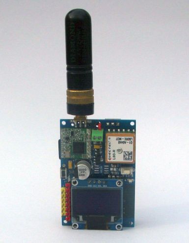
This is my board; code is compatible ??
Ah, I was thinking the other TTGOs, should pay more attention …
The program however does have a Settings file which allows the pins the GPS is accessed on to be changed, you would probably need to change the pin allocations to;
#define GPSTX 15 //pin number for TX output from Arduino - RX into GPS
#define GPSRX 12 //pin number for RX input into Arduino - TX from GPS
Reference Arduino/ESP32 sketch from the TTGO T-Beam V1.0 manufacturer:
Sending this code:
#include <SoftwareSerial.h>
#include <TinyGPS++.h>
#include <axp20x.h>
TinyGPSPlus gps;
SoftwareSerial ss(12,34);
AXP20X_Class axp;
//HardwareSerial Serial1(1);
void setup()
{
Serial1.begin(115200);
ss.begin(9600);
axp.setPowerOutPut(AXP192_LDO3, AXP202_ON);
Serial.begin(9600, SERIAL_8N1, 34, 12); //17-TX 18-RX
}
void loop()
{
while (ss.available() > 0)
gps.encode(ss.read());
Serial.print("Latitude : ");
Serial.println(gps.location.lat(), 5);
Serial.print("Longitude : ");
Serial.println(gps.location.lng(), 4);
Serial.print(“Satellites: “);
Serial.println(gps.satellites.value());
Serial.print(“Altitude : “);
Serial.print(gps.altitude.feet() / 3.2808);
Serial.println(“M”);
Serial.print(“Time : “);
Serial.print(gps.time.hour());
Serial.print(”:”);
Serial.print(gps.time.minute());
Serial.print(”:”);
Serial.println(gps.time.second());
Serial.println(”**********************”);
smartDelay(1000);
if (millis() > 5000 && gps.charsProcessed() < 10)
Serial.println(F(“No GPS data received: check wiring”));
}
static void smartDelay(unsigned long ms)
{
unsigned long start = millis();
do
{
while (Serial1.available())
gps.encode(Serial1.read());
} while (millis() - start < ms);
}
OUTPUT IS:
18:38:33.269 -> **********************
18:38:34.253 -> No GPS data received: check wiring
18:38:34.253 -> Latitude : 0.00000
18:38:34.253 -> Longitude : 0.0000
18:38:34.253 -> Satellites: 0
18:38:34.253 -> Altitude : 0.00M
18:38:34.253 -> Time : 0:0:0
18:38:34.253 -> **********************
//no data are shown
Those pins for the GPS dont match what was shown on the picture of the PCB that you posted …
i’m not sure, but according to TTGO T-Beam v1.0 pin out,
TX = IO34;
RX= IO12
it’s incorrect ??
thank you for support
You tell us, the picture you posted of your board says the GPS pins are 12 and 15, take a look.
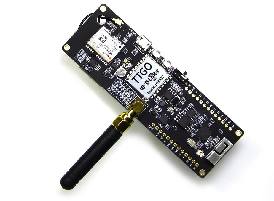
Sorry for misundestanding; the correct picture is availabra here:
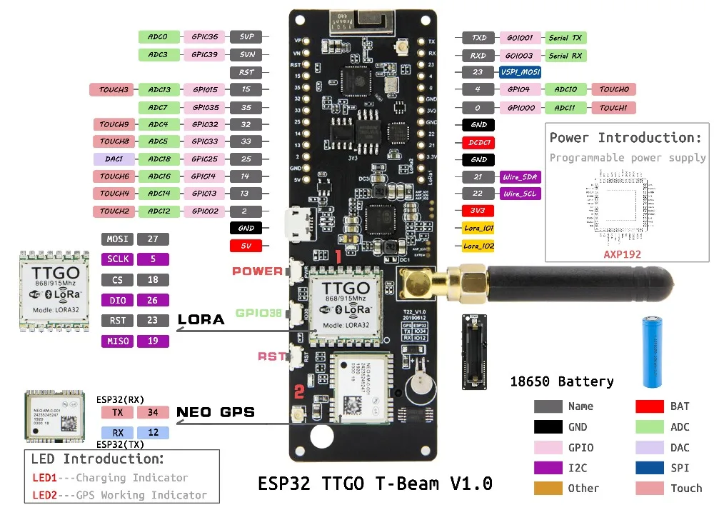
i confirm 
TX = IO34;
RX= IO12;
And the GPS pin label or your real board, the one you actually have, is the same as the new picture ?
And the GPS is outdoors with a good view of the sky ?
This command;
SoftwareSerial ss(12,34);
sets up SoftwareSerial (the ESP32) to receive data on pin 12. That would need to be the TX pin of the GPS.
Can you point us to a description of your TTN mapper (which board, circuit diagram and other information etc.).
I have not published that information as yet.
The board was my own design and build. The software was a straight forward program using TinyLoRa.
Thank you for the information. It would be very nice if you could share your project with us.
Did it work? I’m using the same board and trying to get the GPS Location and its not working 
If you check other topics and posts on this forum you will discover that without (you) providing any detailed information people will not be ably to provide any useful help.
Indeed, ‘its not working’ does not mean much to me either.
When working with programs that use GPSs I would strongly recommend that you actually test that the GPS is working, as in providing the correct fix information, before using the GPS with a node program.
I’m sorry, never used forums to ask for help and report errors/bugs. My bad indeed.
The first question that i would like to ask is. I’m using the TTGO T-Beam board and in my board (physically) it says that the TX and RX pins are IO12 and IO15 (respectively). But I’ve seen some documentation online and it always says 12/34, never seen anyone say 12/15 but I should go with what the board says right?
My second quesiton is, I’m testing the TinyGPS++ device example to test it and the Logs that I get on the Serial Monitor are “No GPS detected: check wiring.”. like I’ve said above, I’ve checked the pinmaps and i tought they were correct (TX-12 and RX-15) so I don’t know what could be de problem
My final question is: On the example we use ss.begin(GPSBaud) where GPSBaud = 4800. I’ve searched for the value that I should use and the results said that the values could go from 4800 to 230400, being 9600 the default value. Those this make any difference at all, and what those it actually do?
Again, I’m sorry for the non detailed information that I’ve given to you.
Thank You!!
Be prepared that we need even more information than what you currently provided. ![]()
No you are not. Topic title says T-Beam v1.0. You won’t have a 1.0 board if it says that the TX and RX pins are IO12 and IO15.
I assume you mean the labeling (‘silkscreen’) on the PCB?
If written on the PCB you can be sure that it should be correct.
Have you actually tried these values?
Based on this information you appear to have some older v0.x board (v05, v0.6, v0.7 or even something else).
The version of the board and a date should be printed on the PCB.
What version (“T22_Vxx”) and date does your board show?
What information does the label on the GPS module show?
There are important differences between different versions of the T-Beam boards.
It is essential to know which version you have.
For pinout diagrams of different versions of the T-Beam boards see: