Hello,
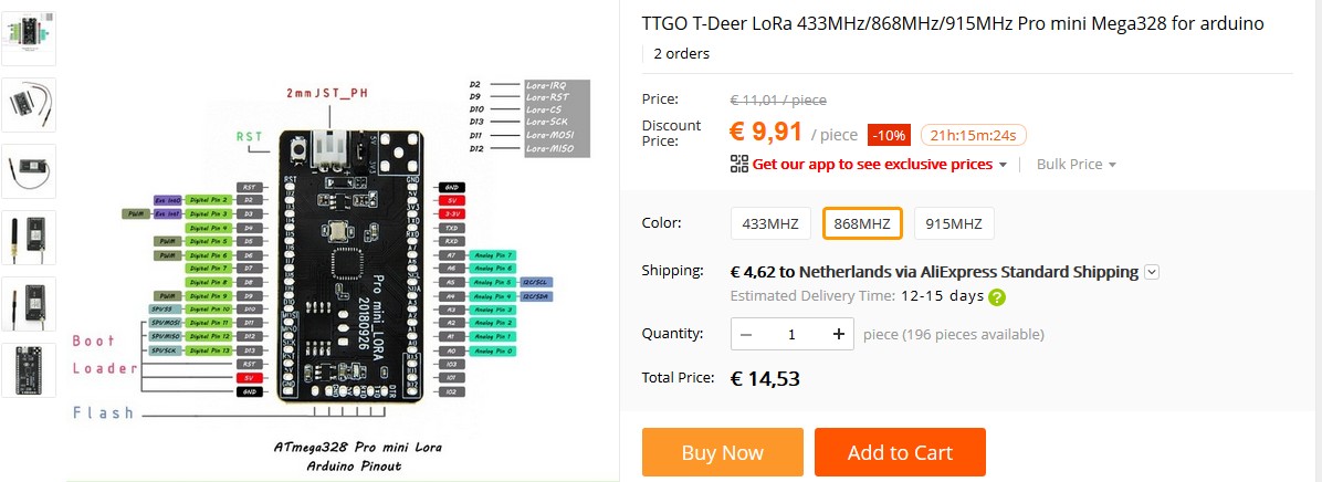
Has somebody of you already used TTGO T-Deer?
Would be great to get some info’s about it - I’d like to use it as cheap LORA WAN end device for a small project.
THX in advance & BR
Hello,
Has somebody of you already used TTGO T-Deer?
Would be great to get some info’s about it - I’d like to use it as cheap LORA WAN end device for a small project.
THX in advance & BR
does it work with lmic ?

As far as I read there is a LMIC variant existing that fits.
But before buying a module I was hoping for more details. Especially topics like power supply and how to program the chip (JTAG or simply via bootloader)
You will need an (USB)-ISP if you want to (re)flash the boot loader. Might not be necessary if the boot loader is already flashed and you are happy with it.
For programming you just need an FTDI.
As far as one can see on the picture it can be powered in 5V or 3V3 (probably need to de-solder the LDO for low-power operation)
Not sure what the 8-pin chip is (QSPI flash?)
Note that there is no evidence that the DIO pins are exposed, so it might be useless for us…
I’m curious, just asked for full schematic - have to see
Hello,
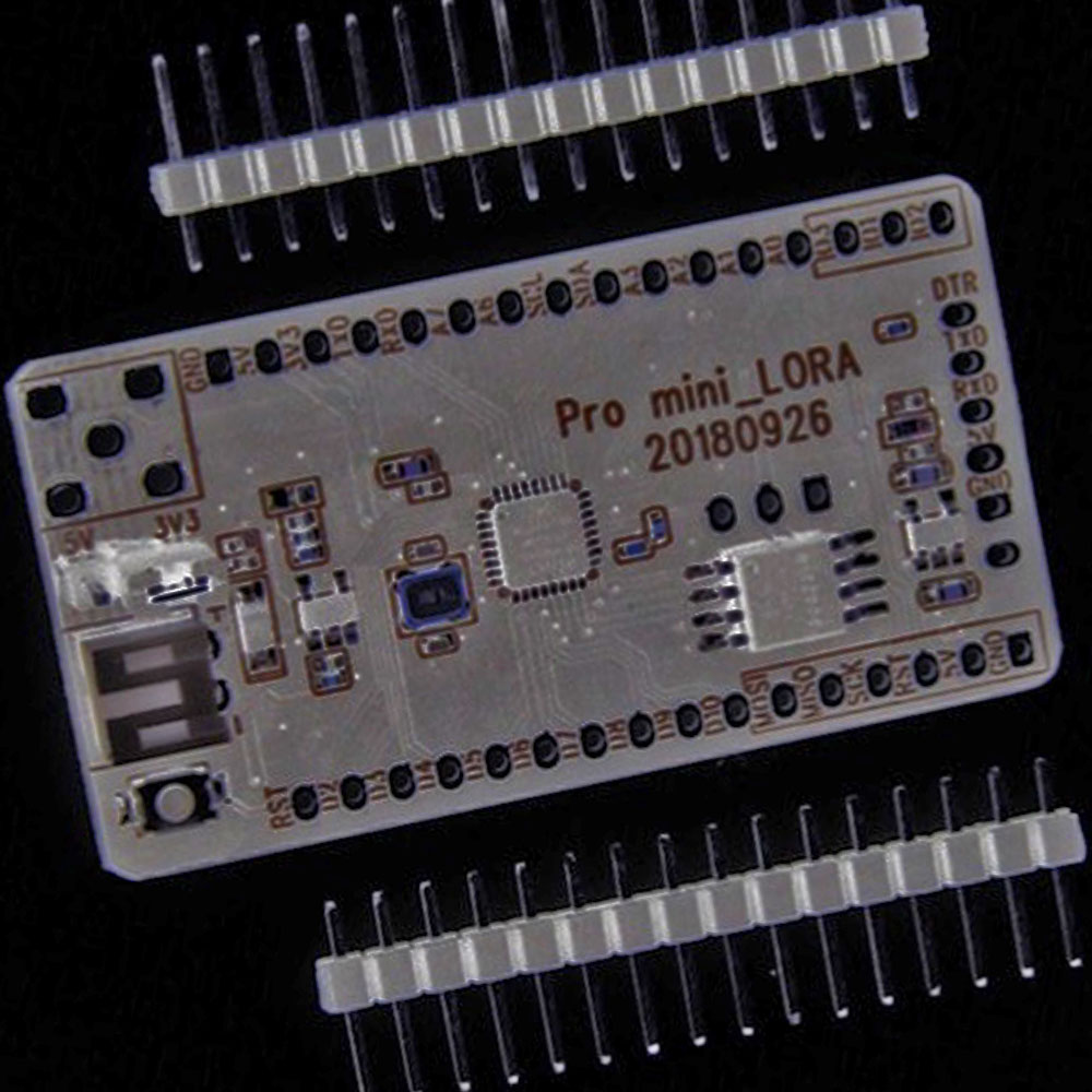
I just receive the shematic of the board - looks promising!
For me this board is a really nice alternative to build up a cheap client without the need of own PCB.
Now the question is still not clear how to program - ISP needed or simply CP2102
pro mini_lora.pdf (55.6 KB)
It is indeed a SPI flash… (W25Q32FV)
Actually they are, just not connected to the AVR, so it is the matter linking these.
CP2102/FTDI for the firmware.
You will need an ISP if you want to change the bootloader…
I was hopeful about this given the price point, not sure how low power its going to be
If you feed it in 3V, it looks like you bypass the regulator and the battery charger (if not, de-solder  )…
)…
So would remain:
So it is probably more than OK from a power perspective…
… but running an ATmega 328p in 3v with a 16MHz clock is out of spec 
(I guess you could change the clock divider fuse to bring it down)
In 5V it would be another story; with the LDO and the battery charger chip, I doubt it will be really low power…
The default fuse setting for CKDIV8 is 0 (which means to me “programmed”) and causes (in my understanding) to divide the clock speed by 8 => remaining frequency = 2MHz
Page 38 of the datasheet says:
The CKDIV8 Fuse determines the initial value of the CLKPS bits. If CKDIV8 is unprogrammed,
the CLKPS bits will be reset to “0000”. If CKDIV8 is programmed, CLKPS bits are reset to
“0011”, giving a division factor of 8 at start up. This feature should be used if the selected clock
source has a higher frequency than the maximum frequency of the device at the present operating
conditions. Note that any value can be written to the CLKPS bits regardless of the CKDIV8
Fuse setting. The Application software must ensure that a sufficient division factor is chosen if
the selected clock source has a higher frequency than the maximum frequency of the device at
the present operating conditions. The device is shipped with the CKDIV8 Fuse programmed.
Another topic makes me nervous: J40
For me it seems that this jumper decides how the ATMEGA328P is being powered.
Let’s assume i want to connect the whole board via J37 to a CP2102 based USB 2 Serial board with 5Volts. Then the whole board get’s powered via USB. If J40 is set to 3V3 the CP2102 would output 5V levels on RXD/TXT but the ATMEGA328P would be powered with 3V3. Is this still working?
Otherwise if i set J40 to 5V, how do the periferals like W25Q32FVSS or HPD13A behave?
This is the chip factory default, to ensure it will be programmable at almost any voltage…
On an Arduino it will typically be flipped so that the avr runs at the clock frequency
Mmmmh… I always use my FTDI at 3.3v…
Right… These are powered in 3v3, but get 5V logic level from the Arduino – that doesn’t sound right to me either…
So only 3.3v would make sense, but then why 16Mhz ![]()
So, FTDI and CP2102 are all on 3.3V, no need to care about the level…
But then the jumper J40 is completely useless…
Regarding the 16MHz i would say: simply change Arduino to prescale by 2 and result finally in 8MHz.
Just ordered 6 to have a play with, has anyone else actually got one tested yet?
Ordered yesterday a bunch…
Wait and see 
For the time being I stick to @Charles Mini-Lora nodes – I have more than enough parts for my current needs 
But still curious to see these can get power under control…
While waiting for the board i start creating a suitable bootloader. The 16MHz are not what i want to have in bad battery conditions. So I want to modify to run optiboot on 2MHz (CKDIV8 fuse)
The main program shall switch the Clock Division Factor back to 2 to run finally on 8MHz.
…
Sorry for my bad English
When I connect the Pro mini_LORA to a TTL, messages are immediately output to the Serial Monitor. There is obviously a demo sketch. Unfortunately, this assignment of RX / TX can not play a new sketch. I have not succeeded with ISP either. Does anyone have the part to run?