Hi there,
I´m using a TTGO LoRa OLED v1 board and the ttn-abp sketch to send data to the platform and a Pycom LoPy nanogateway. The gateway is properly conneted, it always shows online and with recent timestanps in the “Last Seen” field.
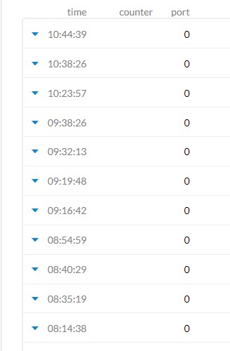
The problem I´m having is I do not receive data in a constant way. A message may take 3 minutes, of 15, perhaps an hour passes by before receiving another one. The code configuration is set to 60 seconds.
Here is a little demonstration:
Here is my code is this:
#include <lmic.h>
#include <hal/hal.h>
#include <SPI.h>

//
// For normal use, we require that you edit the sketch to replace FILLMEIN
// with values assigned by the TTN console. However, for regression tests,
// we want to be able to compile these scripts. The regression tests define
// COMPILE_REGRESSION_TEST, and in that case we define FILLMEIN to a non-
// working but innocuous value.
//


// LoRaWAN NwkSKey, network session key
// This should be in big-endian (aka msb).
static const PROGMEM u1_t NWKSKEY[16] = { 0x0C, 0x53, 0x5C, 0x6D, 0x84, 0x73, 0x0F, 0x98, 0xCE, 0xB1, 0xC4, 0x86, 0x02, 0xB4, 0xE4, 0x24 };

// LoRaWAN AppSKey, application session key
// This should also be in big-endian (aka msb).
static const u1_t PROGMEM APPSKEY[16] = { 0x85, 0xED, 0xCA, 0x46, 0x51, 0xF8, 0x4E, 0x0B, 0x6C, 0xE5, 0xB2, 0x5B, 0x46, 0x15, 0x1E, 0x5B };

// LoRaWAN end-device address (DevAddr)
// See http://thethingsnetwork.org/wiki/AddressSpace
// The library converts the address to network byte order as needed, so this should be in big-endian (aka msb) too.
static const u4_t DEVADDR = 0x226011FF2; // <-- Change this address for every node!

// These callbacks are only used in over-the-air activation, so they are
// left empty here (we cannot leave them out completely unless
// DISABLE_JOIN is set in arduino-lmic/project_config/lmic_project_config.h,
// otherwise the linker will complain).
void os_getArtEui (u1_t* buf) { }
void os_getDevEui (u1_t* buf) { }
void os_getDevKey (u1_t* buf) { }

static uint8_t mydata[] = "Hi";
static osjob_t sendjob;

// Schedule TX every this many seconds (might become longer due to duty
// cycle limitations).
const unsigned TX_INTERVAL = 60;

// Pin mapping
// Adapted for Feather M0 per p.10 of [feather]
const lmic_pinmap lmic_pins = {
  .nss = 18,
  .rxtx = LMIC_UNUSED_PIN,
  .rst = 14,
  .dio = {/*dio0*/ 26, /*dio1*/ 33, /*dio2*/ 32}
};

void onEvent (ev_t ev) {
    Serial.print(os_getTime());
    Serial.print(": ");
    switch(ev) {
        case EV_SCAN_TIMEOUT:
            Serial.println(F("EV_SCAN_TIMEOUT"));
            break;
        case EV_BEACON_FOUND:
            Serial.println(F("EV_BEACON_FOUND"));
            break;
        case EV_BEACON_MISSED:
            Serial.println(F("EV_BEACON_MISSED"));
            break;
        case EV_BEACON_TRACKED:
            Serial.println(F("EV_BEACON_TRACKED"));
            break;
        case EV_JOINING:
            Serial.println(F("EV_JOINING"));
            break;
        case EV_JOINED:
            Serial.println(F("EV_JOINED"));
            break;
        /*
        || This event is defined but not used in the code. No
        || point in wasting codespace on it.
        ||
        || case EV_RFU1:
        ||     Serial.println(F("EV_RFU1"));
        ||     break;
        */
        case EV_JOIN_FAILED:
            Serial.println(F("EV_JOIN_FAILED"));
            break;
        case EV_REJOIN_FAILED:
            Serial.println(F("EV_REJOIN_FAILED"));
            break;
        case EV_TXCOMPLETE:
            Serial.println(F("EV_TXCOMPLETE (includes waiting for RX windows)"));
            if (LMIC.txrxFlags & TXRX_ACK)
              Serial.println(F("Received ack"));
            if (LMIC.dataLen) {
              Serial.println(F("Received "));
              Serial.println(LMIC.dataLen);
              Serial.println(F(" bytes of payload"));
            }
            // Schedule next transmission
            os_setTimedCallback(&sendjob, os_getTime()+sec2osticks(TX_INTERVAL), do_send);
            break;
        case EV_LOST_TSYNC:
            Serial.println(F("EV_LOST_TSYNC"));
            break;
        case EV_RESET:
            Serial.println(F("EV_RESET"));
            break;
        case EV_RXCOMPLETE:
            // data received in ping slot
            Serial.println(F("EV_RXCOMPLETE"));
            break;
        case EV_LINK_DEAD:
            Serial.println(F("EV_LINK_DEAD"));
            break;
        case EV_LINK_ALIVE:
            Serial.println(F("EV_LINK_ALIVE"));
            break;
        /*
        || This event is defined but not used in the code. No
        || point in wasting codespace on it.
        ||
        || case EV_SCAN_FOUND:
        ||    Serial.println(F("EV_SCAN_FOUND"));
        ||    break;
        */
        case EV_TXSTART:
            Serial.println(F("EV_TXSTART"));
            break;
        case EV_TXCANCELED:
            Serial.println(F("EV_TXCANCELED"));
            break;
        case EV_RXSTART:
            /* do not print anything -- it wrecks timing */
            break;
        case EV_JOIN_TXCOMPLETE:
            Serial.println(F("EV_JOIN_TXCOMPLETE: no JoinAccept"));
            break;
        default:
            Serial.print(F("Unknown event: "));
            Serial.println((unsigned) ev);
            break;
    }
}

void do_send(osjob_t* j){
    // Check if there is not a current TX/RX job running
    if (LMIC.opmode & OP_TXRXPEND) {
        Serial.println(F("OP_TXRXPEND, not sending"));
    } else {
        // Prepare upstream data transmission at the next possible time.
        LMIC_setTxData2(1, mydata, sizeof(mydata)-1, 0);
        Serial.println(F("Packet queued"));
    }
    // Next TX is scheduled after TX_COMPLETE event.
}

void setup() {
//    pinMode(13, OUTPUT);
    while (!Serial); // wait for Serial to be initialized
    Serial.begin(115200);
    delay(100);     // per sample code on RF_95 test
    Serial.println(F("Starting"));

    #ifdef VCC_ENABLE
    // For Pinoccio Scout boards
    pinMode(VCC_ENABLE, OUTPUT);
    digitalWrite(VCC_ENABLE, HIGH);
    delay(1000);
    #endif

    // LMIC init
    os_init();
    // Reset the MAC state. Session and pending data transfers will be discarded.
    LMIC_reset();

    // Set static session parameters. Instead of dynamically establishing a session
    // by joining the network, precomputed session parameters are be provided.
    #ifdef PROGMEM
    // On AVR, these values are stored in flash and only copied to RAM
    // once. Copy them to a temporary buffer here, LMIC_setSession will
    // copy them into a buffer of its own again.
    uint8_t appskey[sizeof(APPSKEY)];
    uint8_t nwkskey[sizeof(NWKSKEY)];
    memcpy_P(appskey, APPSKEY, sizeof(APPSKEY));
    memcpy_P(nwkskey, NWKSKEY, sizeof(NWKSKEY));
    LMIC_setSession (0x13, DEVADDR, nwkskey, appskey);
    #else
    // If not running an AVR with PROGMEM, just use the arrays directly
    LMIC_setSession (0x13, DEVADDR, NWKSKEY, APPSKEY);
    #endif

    #if defined(CFG_eu868)
    // Set up the channels used by the Things Network, which corresponds
    // to the defaults of most gateways. Without this, only three base
    // channels from the LoRaWAN specification are used, which certainly
    // works, so it is good for debugging, but can overload those
    // frequencies, so be sure to configure the full frequency range of
    // your network here (unless your network autoconfigures them).
    // Setting up channels should happen after LMIC_setSession, as that
    // configures the minimal channel set. The LMIC doesn't let you change
    // the three basic settings, but we show them here.
    LMIC_setupChannel(0, 868100000, DR_RANGE_MAP(DR_SF12, DR_SF7),  BAND_CENTI);      // g-band
    LMIC_setupChannel(1, 868300000, DR_RANGE_MAP(DR_SF12, DR_SF7B), BAND_CENTI);      // g-band
    LMIC_setupChannel(2, 868500000, DR_RANGE_MAP(DR_SF12, DR_SF7),  BAND_CENTI);      // g-band
    LMIC_setupChannel(3, 867100000, DR_RANGE_MAP(DR_SF12, DR_SF7),  BAND_CENTI);      // g-band
    LMIC_setupChannel(4, 867300000, DR_RANGE_MAP(DR_SF12, DR_SF7),  BAND_CENTI);      // g-band
    LMIC_setupChannel(5, 867500000, DR_RANGE_MAP(DR_SF12, DR_SF7),  BAND_CENTI);      // g-band
    LMIC_setupChannel(6, 867700000, DR_RANGE_MAP(DR_SF12, DR_SF7),  BAND_CENTI);      // g-band
    LMIC_setupChannel(7, 867900000, DR_RANGE_MAP(DR_SF12, DR_SF7),  BAND_CENTI);      // g-band
    LMIC_setupChannel(8, 868800000, DR_RANGE_MAP(DR_FSK,  DR_FSK),  BAND_MILLI);      // g2-band
    // TTN defines an additional channel at 869.525Mhz using SF9 for class B
    // devices' ping slots. LMIC does not have an easy way to define set this
    // frequency and support for class B is spotty and untested, so this
    // frequency is not configured here.
    #elif defined(CFG_us915) || defined(CFG_au915)
    // NA-US and AU channels 0-71 are configured automatically
    // but only one group of 8 should (a subband) should be active
    // TTN recommends the second sub band, 1 in a zero based count.
    // https://github.com/TheThingsNetwork/gateway-conf/blob/master/US-global_conf.json
    LMIC_selectSubBand(1);
    #elif defined(CFG_as923)
    // Set up the channels used in your country. Only two are defined by default,
    // and they cannot be changed.  Use BAND_CENTI to indicate 1% duty cycle.
    // LMIC_setupChannel(0, 923200000, DR_RANGE_MAP(DR_SF12, DR_SF7),  BAND_CENTI);
    // LMIC_setupChannel(1, 923400000, DR_RANGE_MAP(DR_SF12, DR_SF7),  BAND_CENTI);

    // ... extra definitions for channels 2..n here
    #elif defined(CFG_kr920)
    // Set up the channels used in your country. Three are defined by default,
    // and they cannot be changed. Duty cycle doesn't matter, but is conventionally
    // BAND_MILLI.
    // LMIC_setupChannel(0, 922100000, DR_RANGE_MAP(DR_SF12, DR_SF7),  BAND_MILLI);
    // LMIC_setupChannel(1, 922300000, DR_RANGE_MAP(DR_SF12, DR_SF7),  BAND_MILLI);
    // LMIC_setupChannel(2, 922500000, DR_RANGE_MAP(DR_SF12, DR_SF7),  BAND_MILLI);

    // ... extra definitions for channels 3..n here.
    #elif defined(CFG_in866)
    // Set up the channels used in your country. Three are defined by default,
    // and they cannot be changed. Duty cycle doesn't matter, but is conventionally
    // BAND_MILLI.
    // LMIC_setupChannel(0, 865062500, DR_RANGE_MAP(DR_SF12, DR_SF7),  BAND_MILLI);
    // LMIC_setupChannel(1, 865402500, DR_RANGE_MAP(DR_SF12, DR_SF7),  BAND_MILLI);
    // LMIC_setupChannel(2, 865985000, DR_RANGE_MAP(DR_SF12, DR_SF7),  BAND_MILLI);

    // ... extra definitions for channels 3..n here.
    #else
    # error Region not supported
    #endif

    // Disable link check validation
    LMIC_setLinkCheckMode(0);

    LMIC_setClockError(MAX_CLOCK_ERROR * 10 / 100);
    // TTN uses SF9 for its RX2 window.
    LMIC.dn2Dr = DR_SF9;

    // Set data rate and transmit power for uplink
    LMIC_setDrTxpow(DR_SF7,14);

    // Start job
    do_send(&sendjob);
}

void loop() {
    unsigned long now;
    now = millis();
    if ((now & 512) != 0) {
      digitalWrite(13, HIGH);
    }
    else {
      digitalWrite(13, LOW);
    }

    os_runloop_once();

}
Any gueses?
Thanks in advance
Tomás
