TTN Mapper only records strong signals or nothing

Hi Forum,
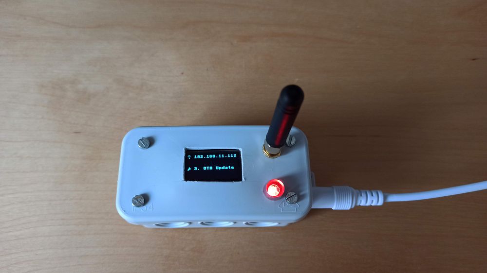
I’m relatively new to LoRaWAN (but not to electronics and software). I installed a gateway in my house, prepared a EPS32 based test-board and registered all with TTN. Then I did some coverage test by using the TTN-Mapper Android App.


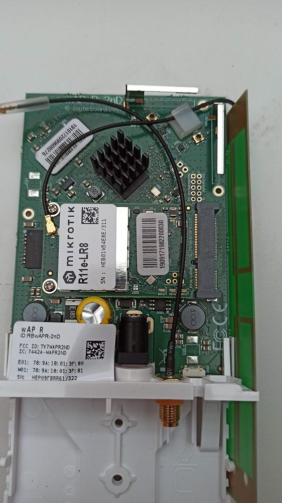
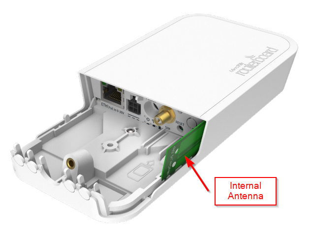
I was a bit disappointed by the results. But maybe that’s OK, because the gateway is located inside (though on roof level) and uses currently the built-in antenna.
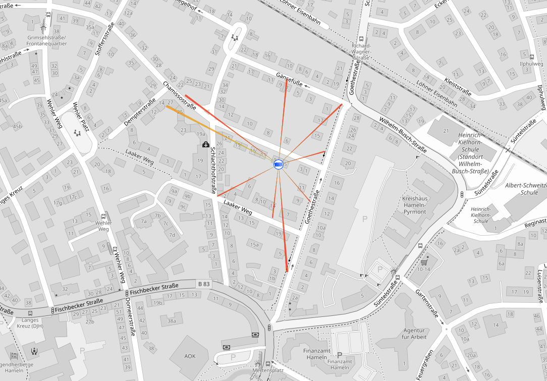
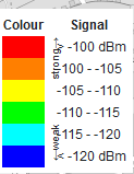
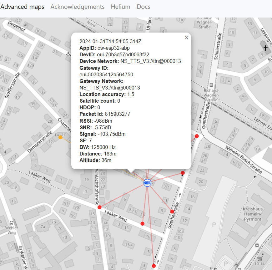
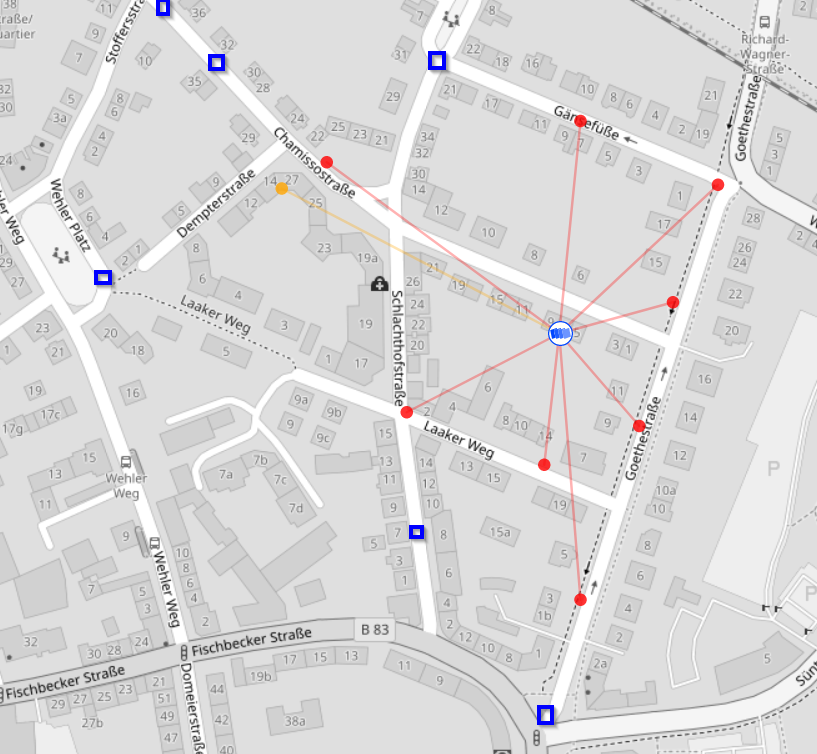
But what makes me wonder is the fact, that I was only able to record high RSSI signals (in the attached screen-shot only red and a few orange beams). I would have expected to see - moving away from the gateway - after strong signals medium signals, finally weak signals and only then loose the connection to the gateway. But for me it was strong signals or nothing.
Is my expectation wrong?
Is there something one can do wrong while doing the measurement?
Could it be a configuration issue? For me it looks like I have checked somewhere “accept only strong signals”, though I’m not aware of any setting in that direction.

Thank you for your suggestions!
Christian

Red & Orange are good names for Reservoir Dogs but aren’t numbers so it’s hard to be specific.

When the device is at home just outside, what signal measurements do you get? That provides a benchmark, as the other tracks appear to have to go through houses …

Plus all the other information, literally everything you can possibly think of, gateway make & model, antenna, where inside is the antenna, you say roof level, what is the roof made of, are you in a dip or on a hill, what is the antenna on the ESP32 board, what is the board, what is the firmware, how are you connecting, is this on SF7, is ADR on, etc etc etc.

RF is a dark art, like Professor Snape type dark art - outside your house you may be under the antennas polar - like being under an umbrella, so you may have to try smaller distances away your own street.

Hi Descartes,
Thank you for your reply.

OK, but there are numbers to the colors in the TTN mapper legend.
2024-02-01_TTN Coverage_legend

That is an explanation, what influences the actual signal strength and coverage, correct? You don’t ask actually for all that information, right?

I fully understand that it is close to impossible to judge the actual signal strength I have measured. My question was more about the relative results.
I was looking for an explanation, why I measured (as an example) 200m away from the gateway a signal strength of >-100 dBm (to stick to numbers instead of colors :slightly_smiling_face:) but 250m away I lost connection completely. My expectation was to see also coverage events somewhere between -105 dBm … -120 dBm. Even more since it was the same in all directions around the gateway: strong signal (> -105 dBm) here, no signal some 10m further away. I never got a measurement with a signal between -105 dBm and -120 dBm.

The Mitte area is relatively flat and consistent from topology POV (66-74m ASL?) so as Nick says it will be down to your RF implementations and deployment. The two factors outside yor immediate control will be building clutter and the Sat view - TTNMapper also puts a ‘cut’ on the quality of the sat feed based on HDOP value. Experience also shows that you cant map an area on one trip (unless walking very slowly!), given TX duty cycles & FUP so do multiple go arounds and look at aggregate coverage over time. Also where TTNMapper guidance is to do at SF7 that is frankly doing LoRa/LoRaWAN a diservice and would limit local GW capacity and undercall the real capabilities so repeat at say SF8 & SF9 and see how coverage varies (adjusting repetion rate to keep with FUP as you go of course :wink: )

See
https://avbentem.github.io/airtime-calculator/ttn/eu868/10

Thank you, I think, I was not aware of that, but specific numbers please. Actual numbers!

Actually yes, because any one detail may influence the volunteers giving up their time to answer your question. Choices of gateway, antenna, device, settings, it’s all in the mix. So much easier for you to quickly list your kit than for us to take until post #20 to find out something isn’t as expected.

RF is perfectly logarithmic in a vacuum. In reality a large delivery truck can stop transmissions arriving whilst it’s parked up at a particular location and then drive off. Or a microwave was in use. Hence doing mapping more than once.

Erm, that’s in the console for both gateway & device, so quite the opposite!

Likely that will be the effect of building clutter, absorbers and reflections. Lets consider for example one of your data points - say the orange track to west north west which is reasonable. I can imagine that outside your property as you walked/cycled/drove ‘westerly’ down Chamissostr you would likely have a very strong signal which gradually fell to the junction with Chalachthostr by which time the subtended angle would have had your signal having to go through the row of intervening buildings…going past the ‘curved’ deployment of buildings north of the Jorg Emil Muller Klinik it would get worse to the point where as you turn down Dempterstr you get the last signal (orange?) before then finding the accumulation of signal absorption through all the buildings finally cuts you off!

Do that run multiple times and you will find ‘gaps’ where the clutter is less impactful and signals will eventually get through. Short chirps are more prone to loosing signal due to say reflections where longer chirps (higher SF’s) allow more time on air and more time to discriminate signals and capture symbols - LoRa very god a reconstruction even when up to half of symbols are lost so SF8 & 9 likely will show better coverage :slight_smile:

BTW for ‘real data’ you dont even need the console - in TTNMapper if you hover exactly over the signal trace ‘ray’ on the map ((you may have to click IIRC) you will be presented with all the RSSI/SNR and Distance data for example for that specific ‘hit’

1 Like

OK, I guess I understood your messages (I’m not a native English speaker, hence it’s important for me to check regularly, if I have understood posts correctly):

  • what I have measured might be correct (though I’m still a bit puzzled that I had the same micro wave, delivery truck, building clutter, what ever - effect at every spot around my gateway)
  • I should repeat the measurement more often (of course by respecting the FUP :smiling_face:)
  • it’s hard to tell, if the measured RSSI is good / realistic, expectable without having more details

What I meant was that it is hard to tell whether a measured signal strength, even having precise numbers, is good / bad, what one can expect, can be improved etc. In the end there are no micro waves, delivery trucks etc. in my data.

I fully understand stand and respect the service you are giving to beginners like myself. My thinking was, that I don’t expect you to answer a question, where so much detailed information is needed.

Oh, is it? Actually I was looking for that, but was not able to find it. Are you talking about the web interface (https://ttnmapper.org/) or the Android App? I wasn’t able to find it in both. What do you mean by IIRC? If I remember correctly? First I thought it is a technical term like RSSI :grinning:

I dont use the App, this is an example hit from this afternoon on the TTN Mapper website for a development tracker pinging an iMST GW with an indoor ant (sadly looses around 5-6db) on SF8 at just under 2km:

image

Indeed IIRC = if I remember correctly, or if I Recall :slight_smile:

It wont be every spot - it will vary with the building clutter (and construction types etc.) as you move around. Your Microtik GW, even with internal Ant should be performing ok (I have one here that does just fine even though its mounted indoor as a test unit) just make sure device is mounted vertical - not flat on a desk or shelf! - and also as you walk around with your node make sure its Ant also kept vertical - if not you could be loosing 7-10db just by mis-alignment :slight_smile: If war driving with node in a vehicle make it has clear view out of windows to see sat and to send without restriction to your GW (again be aware of orientation… a simple walk test along route above then perhaps back along the Laaker Weg path at the SW end of Dempterstr then Laaker Weg proper and back up via Goethestr should inform you a lot abour radial coverage from you base. Range should then be from 50 to approx 250/300m in suburban environment which shold give reasonal coverage if not perfect…

Quick note that this only works on an “Advanced map” - the Heatmap is too crowded usually so it’s not available on that view. Instead, on the Advanced map, you can enter the Device ID or Gateway ID of your device/gateway, and you will end up with a map of only the relevant data. As this is usually much less information, it actually gives you all sorts of lines which are indeed clickable! As you can see in Jeff’s screenshot.

My bad - I forgot to say this - OP’s map with the beams looked like the advanced map and I failed to check

This is the orange plot in question!
image
Obviously no sat or HDOP values as using the App! Given building clutter 95-100dBm isnt bad at that point but gives <200m range :wink:

Again, very much the opposite. If you give us a list right from the beginning of the kit you are using, either we’ve seen it before and can factor it in or tell you if it is likely to give you issue, or we haven’t seen it before and look at the details. Takes about 10 seconds to scan down the list and saves what is now post number 3 asking for information which would help us to help you. Thereby taking even longer. You’re not my first rodeo, we are very very experienced at answering questions and we know what we need for particular types - like this open ended one that may be explained in a heart beat if we had the info to hand.

So at the moment we are still none the wiser and are therefore still guessing. If it turns out you have one of the “special” products it may make all the difference. Or even an issue with an SMA connector that turns out to be female to female. Or any number of other things we’ve seen over the years.

RSSI > -50 is a bit loud, < -110 is a bit low. It runs in between. I assume you have the X-Ray vision upgrade for any passing vehicles & EM generators (microwaves) being used in neighbours houses whilst you are on other streets :wink:

If you put the gateway in the window that allows you the best line of sight, that should suffice to get an idea of how the distance affects the RSSI.

Pretty cool, something more I learned from this conversation! Using the Advanced map I can see it, too.

OK, I see, you really want know it!
Gateway
MikroTik LoRaWAN - wAP LoRa8 kit
Using the internal PCB Antenna
Mikrotik_ant
It’s mounted on a stand in a vertical position.
The roof has (from inside to outside) some kind of dry wall, probably some insulation material, wood, roof tiles.
I think, as Jeff already notice, my house is in a more or less flat area.

Test Device
The testboard is a Heltec ESP32 WiFi Lora V2.
The firmware is very much based on the example “ttn-abp” from the Arduino MCCI LoRaWAN LMIC library. Just some adjustments regarding the display and an LED. I mounted in a housing with the kits external antenna. I kept the antenna vertical during the test.
This is how it looks:
heltec_esp32_lora_test
It was powered from a USB power bank.

I used SF7.
Not sure about the questions “how are you connecting” and “is ADR on”.

I completely agree. But that’s basically what my questions was about. It’s not bad at all the measured points! But at other points, close by, it was so bad, that I wasn’t able to get a connection at all.
Here are points (blue squares) where I did the other, unsuccessful measurement (from what I remember cause nothing is recorded).
TTN Coverage_mesurements
That’s what I tried to say: Not a single attempt to measure a few 10m away from a red circle (> -100dBm) gave a recording, not even with a weak signal. The difference between strong signal and no signal is only a few meters, the behavior is a bit too black and white (or binary, if you want so) in my mind. But as I said, my expectations might be wrong.

1 Like

For funzies, here is an image someone recently sent me, comparing the Heltec included antenna (on the left) to the TTGO included antenna (on the right). Please note that the TTGO isn’t good by any stretch of the imagination - the ±15cm antennae are usually much better.
IMG-20240201-WA0005

1 Like

The conversation is a bit moot at this point as the only time you get near perfect spherical isotropic coverage is in a open field with clear line of sight in reasonably close proximity …and even then…no!

Not sure what you are expecting? What we nor you know is the construction materials of the various buildings and the points you call out and whether reflections may help or degrade etc. What we (or atleast I) dont know is the behavior of the LoRa Node + App combination (@jpmeijers can perhaps input and guide us here!) in that does it have a threshold cut? Perhaps if signal is below a specific threshold (perhaps in association with an SNR limit) does signal get through but then get dumped by the TTNMapper system as perhaps not ‘good enough’ etc. That might explain what you see wrt sudden drop off…

Also another test is to compare your node Tx info with the GW logs of received packets (from your specific node/DevAddr - correlated to timestamps so you know when/where to compare) and see if again received at GW but then perhaps cut from back end. Also do yourself a favour and try at SF8 & SF9 (adjusting to keep within FUP wrt repetition rate etc.) and do an overlay mapping and see how pattern develops… GW capacity and range for LoRaWAN in a given area isnt just based on SF7 but rather reflects the aggregate across all SF’s with a balanced high capacity deployment utilising all available options…

And finally try a mapper/tracker where the actual GPS location is sent with the message so you know they correlate and can see full info in TTN GW and Application consoles. Also capture data to an alternative mapping system so you can eliminate any platform related foibles. With all this you should gradually build an overview of coverage in the area…

Any recommendations?

Do you have an advice about such a system?

At this point I would really like to thank you for your support :pray:!
I really appreciate the time you spent for the detailed information and looking in depth at my case.
I did the exercise for educational reasons (I guess I will not place sensors in my neighbors gardens, but I will play a technical role in a smart city citizen project). You made it this educational experience!

My first reaction to the picture in the first post is: your antenna is not plugged in!

And looking further I see you are using the Mikrotik, which does have an internal antenna, but by default those have the external SMA connector wired in, and the internal antenna disconnected.

Please check that the internal antenna is actually plugged in.

Explanation:
The image of the red beams I see is typical for a gateway with no antenna. Where the traces on the PCB and the SMA connector has to act as an antenna. That works while you are in the RF near field, but as soon as you exit the near field, the signal strength drops very rapidly.

Note:
From experience we know the internal antenna in the Mikrotik is bad. We always use that gateway rather with an external antenna like this one.

Also what has already been mentioned is that you do not know all the building materials that are used. Metallic foil as heat insulation is common - even on windows. By installing a gateway indoors you basically put it inside a microwave oven - nicely shielded in a Faraday cage.

Take it outside and get it higher up - just above the neighbouring buildings. If you keep it indoors, the signal does not only have to travel through your walls and windows, but also through all other buildings and trees in your neighbourhood. If you do the link budget calculation (search for Remco / PE1MEW’s videos), you’ll see the signal won’t go far as soon as there is an obstacle in the way.

See:

1 Like

No filtering in the app. So all data should be forwarded to TTN Mapper and be seen under Advanced Maps. It’s only the aggregated views (Heatmap, Beams) that does some filtering.

Thank your for your input!

I was aware that by default the SMA connector is wired, I changed it to the internal antenna.
After your advice I opened the gateway again, just to double-check.
But it looks correct to me:
gateway_int_ant

Yes, sure. It’s just some more work needed to mount an external antenna outside and high.
My idea was also to have a comparison between the scenarios “indoor / internal antenna” and “outdoors / proper antenna”.

Yes, sure, therefore I didn’t questioning the absolute coverage range that much, but was thinking more about what you called “the signal strength drops very rapidly”. And it seems to me that you had similar thoughts, therefore the question about the not connected antenna.