Sure, @gonzalocasas, although I thought, I had provided all information I have. Actually immediately after uploading the compiled sketch to my uno I get in serial monitor:
I was checking the LMIC source a bit and this error style comes from the hal_failed function, which is basically triggered by ASSERT. In this case, the assert that fails is: ASSERT( (readReg(RegOpMode) & OPMODE_MASK) == OPMODE_SLEEP ) (source), but I am not sure what that means. Perhaps as you said, the shield is defective.
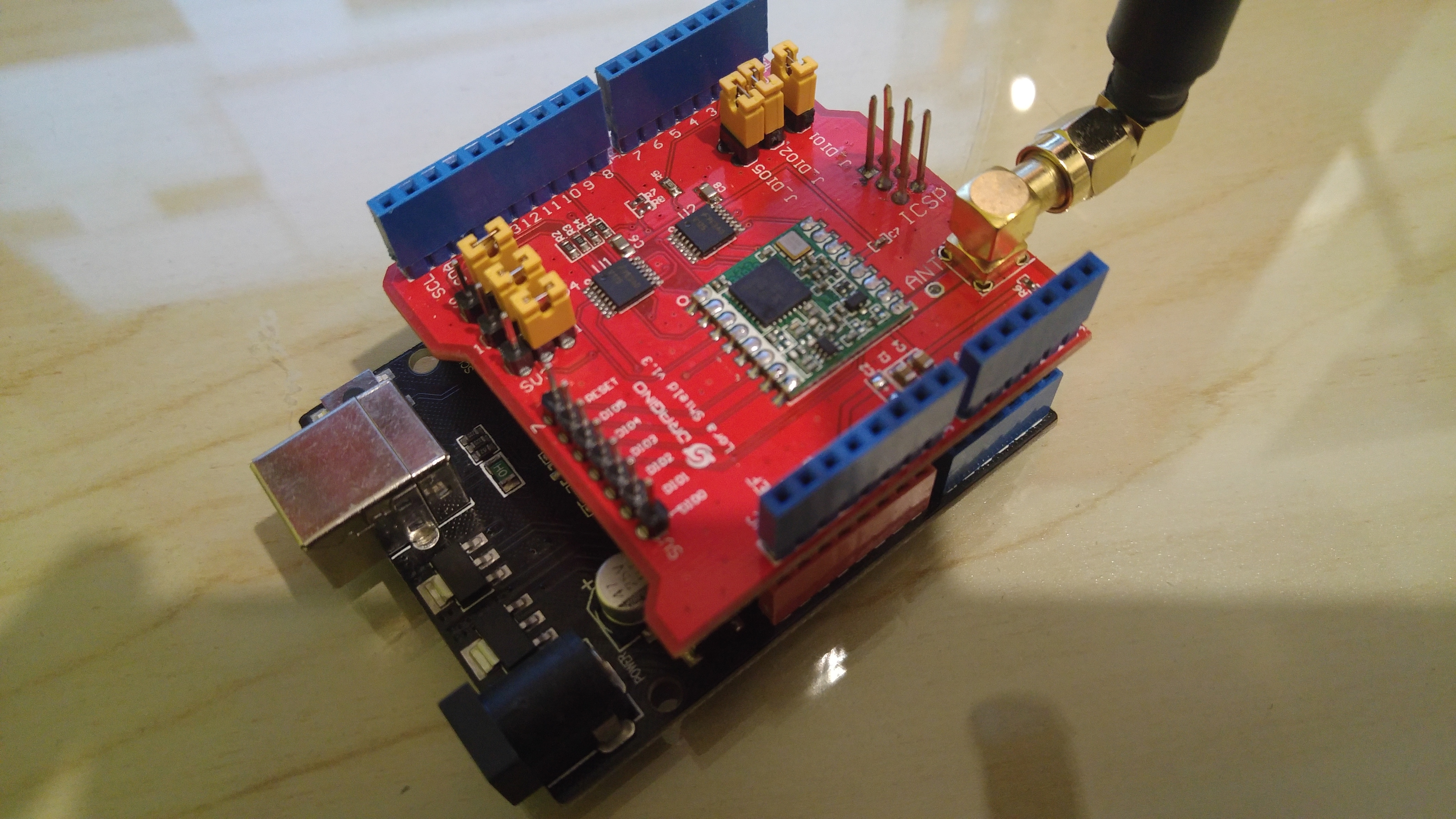
Thanks to @ursm I am finally sure that there is something wrong with my dragino shield. Even using same libraries and sources, same jumper settings I still get an error at that point where radio.c tries to determine whether it is sx1276 (0x12) or 1272 (0x22) chip. Guess it’s broken.
I’m having the same issue, even with the pins set.
also make sure config.h is set correctly
#define CFG_sx1272_radio 1 <–this is my radio uncomment it
// This is the SX1276/SX1277/SX1278/SX1279 radio, which is also used on
// the HopeRF RFM95 boards.
// #define CFG_sx1276_radio 1 <-- not my radio comment it out
further edit, try using the radiohead library and see how you go with that, looks like it is working…
That also did not help, @mikey0000. I am sure now that the shield is broken. I am going to order another one, hoping that the next time everything is going to be working out.
It’s the v1.3 version, @mikey0000, as I intended to write on the topic (but messed that up). It’s the 868 MHz-Version. You are right, I should try the readiohead-lib, which at the moment isn’t what I would call familliar to me. But, if it would work, would I be able to connect to TTN using radiohead lib? Anyway, I will check that.
Dunno about connecting to TTN with Radiohead lib but if it runs, its probably not broken. Also enable debugging messages if you try again with the LMIC lib, I had the same issue as you but as soon as I changed the lmic_pins it started working (I know you’ve tried this already). Make sure you do not change the jumpers.
Just for future references: the shield WAS broken. I meanwhile got a new one and it simply works. So keep in mind that this error might indicate there is something wrong with de LORA hardware.
the board is broken. Looks like there’re many copycats of original Dragino board and many of them are bad quality and unchecked. Good ones have a sticker ‘Q.C. Passed’. I’ve got some good ones and them from another store I received 9 boards very bad quality (cold soldered, etc.) and 1 was broken.
The Dragino shields for the Ardunio (versions 1.3 and 1.4) have a flaw. The design includes level shifters to connect the modem to a 5 volt Arduino however Dragino removed the 5 volt connection and instead power the level converter from 3.3volts (and as a consequence, made the level converter useless as a level converter). When connected to a 5 volt UNO, the switching threshold voltage of the Atmega328P processor for a logic 1 (worst case) is 0.6 * VDD = 0.6 * 5 = 3 volts. The level converters voltage out high (minimum) is approximately 3.19 volts at IOH of 50uA. The level converters output high voltage drops as the load current increases. The margin of safely without loading the outputs is just 0.19 volts and that assumes optimal output levels of the UNO’s 3.3 and 5 volt regulators. Assuming these regulators are quality products (and not cheap copies), they each have a tolerance of approximately 0.1 volts for the 5 volt regulator and 0.09 volts for the 3.3 volt regulator. If you factor this in to the calculations there is no margin of safety and you can expect errors as a result.