A materials question for Lex or any of the other clever RF guys here…
I have lots of old coaxial cable I was planning to scrap after I rebuilt my TV antenna. If I take three pieces of the solid copper core, anchor at one end in a vice and twist these tightly from the other end using a drill they form a very stable twisted wire, even more stable if the ends are tinned with solder. OK so it was a quiet night for TV programming yesterday, maybe I need to get out a bit more!
Anyway, in terms of RF and an antenna like this ground plane example, is there a difference in the way this 3 x twisted copper wire will behave compared to solid brazing rod for example?
I have a few N connectors on order so should I try this idea or is it doomed to failure by design?
RF (or any AC current) has the strange effect that it loves to move around the outer skin of a wire so when twisting firmly them tightly i will behave like a solid wire. soldering the ends with will strengthen the wire (preventing any untwisting due o wind vibrations). The only thing you will get when using plain copper wire is a light layer of oxidation. This could on a very small scale change the behavior of the antenna.
One of my main HF antenna’s uses a non solid wire (3 strings iron and 3 strings silver copper wire) as antenna wire. I can’t find any difference in TX or RX between the original solid wire and this 6 string twisted wire.
But like I always say : hamradio so also TTN is all about experimenting. And remember FAIL means First Attempt In Learning.
Yes you can connect the antenna to the gateway with a coax cable and the length of the cable does has his influence.
The longer the cable the more attenuation to be expected. But also the type of cable has his influence.
For example a consumer cable like the RG-58 has a attenuation of 70 dB for a length of 100m at the EU LoRa frequencies. So a cable with a length of 10m would result in a attenuation of almost 7 dB (a -7dB amplification). Meaning that only 20% of the power put into the cable will be fed into the antenna (and vice versa).
When using a better cable like the AirCell 7 coax cable the attenuation for a 10m length will be just 2 dB (a -2dB amplification). Meaning that 63% of the power put into the cable will be fed into the antenna.
Formulas:
dB (power) = 10log(Pout/Pin)
for example :
Pin = 5W Pout = 1W (very heavy cable loses).
db (power) = 10log(1/5) = -6.989 aprx -7 dB
Pout/Pin = 10^( dB (power) / 10 )
for example : Pout/Pin = 10^(-7 dB/10) = 0.1995 aprx 20%.transfer meaning 80% loss.
It sounds like much even with LoRaWAN who has a good signal to noise ratio a RG-58 could work out.
… I am no RF engineer but for 80mm of copper twisted two-up this works very well, great design.
I have no testing equipment so I can’t say how well it is tuned to 868mhz or how accurately I built this but the difference is clear. I was finding over 400m was hard to achieve, even with the node set to SF12 and the portable gateway placed high inside the roof void like this antenna. RSSI was never lower than -120db but it either worked or it didn’t but the range was disappointing.
The result with the same home made ESP8266 gateway in the same less than ideal position (geographically) but using this ground plane antenna is 4-5km already and I haven’t sough out further suitable places to try. The RSSI is agian in the -114 or -117db range so some room left yet I guess?
I may actually put this antenna 5m above my roof on the old TV antenna pole and try it out on the RAK831 for more testing. I suspect there is plenty more to learn about the node transmit antenna too… wonders if Ryanair will be flying to somewhere near the Belgium/Nederland antenna hangout?
Then with 0.25 wavelength radials, the antenna peaks when the vertical radiator is 0.228 wavelength (average over 3 modules). This is shorter than 0.25, but the diameter of the wire etc does reduce the dimensions a bit.
With the radiator at 0.25 wavelength you might loose 2dB or so.
Antenna tests done at 868Mhz, with a LoRa RFM96 as transmitter, antenna directly attached to module, results at 915Mhz should be similar.
I have 3 such DIY GP antennas based on N-type.
And last one I made based on this tutorial - central wire is 76mm and radial wires - 82mm.
And seems this antenna has worst signal than another 2 antennas which have all wires of 82mm.
But there is also the difference - in this 3rd antenna I use copper wire with 2,5mm diameter which is thicker that on other 2 antennas - they have 1.5mm copper wire.
Is it important to have such thin wires or 2,5-3mm also is ok? I think thicker wire better because it hard to bend.
@lex_ph2lb: the best antenna I have is still a badly-home-made GPA according to your instructions, thanks.
While searching around to understand whether radials length in a GPA need to be shortened according to velocity factor, like the vertical element (warning: I am speaking of things totally outside my expertise), I crossed at least two links that suggested that length of radials should be 0.28•λ•velocity factor:
I found similar hints to longer radials in other places.
Did you ever experiment on this (call open to others too )? Today I have built a new version with 92mm radials, however I have yet to compare (It takes some time, I see different RSSI and SNR depending on time, so I have to collect data to average them).
In ideal situations the radials and radiator would be exactly 0.25 * λ.
But in practice a radial is little larger for example 0.28 * λ instead of 0.25 * λ.
So indeed 0.28 •λ•velocity factor is a good start.
But as you see in the last link you include, the angle of the radials is more of importance then the length (although there’ s a optimum).
The velocity factor depends on the λ and the diameter of the used material. I could go into detail there but i would have to work it out in formulas. But when you can read German see page 85 on the link below (watch it : large download)
Thanks, also for the gigantic book, although I do not read German (but formulas are universal). If possible I would just follow a recipe, but curiosity is always on alert on possible optimizations. In my original GPA I followed the sizes you suggested (@BoRRoZ: yes, the very same sketch ).
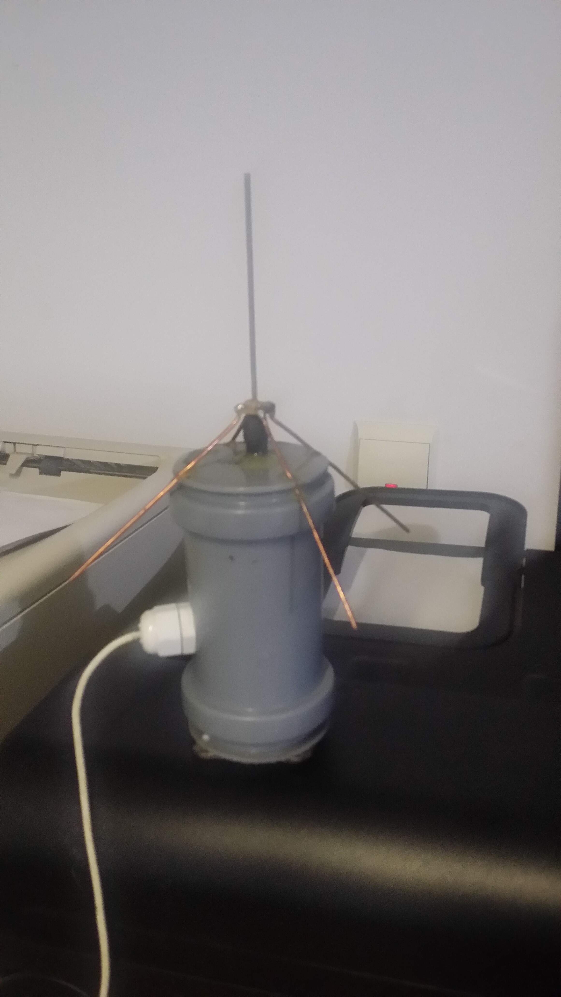
Here is mine, built around a SMA connector and installed on top of some sewage pipe couplings to power a ttn mapper device. Performance is quite impressive, we’ve got a 12.4 km sf7 link in a suburban, hilly area. Setup: arduino pro mini+rfm95w+NEO-6M GPS.
Results here: https://ttnmapper.org/special.php?node=testboardrfm95w&date=2019-06-30&gateways=on
Well, that sewage stuff, even if looks shitty, is providing very cheap yet reliable enclosures. I’m using them since years back for all kind of outdoor protos. However, I’m a little bit ashamed to carry it on my car’s roof By the way, it has two HDD magnets on bottom side… Thanks for appreciating and thanks a million for sharing antenna plans.

 but I will post something here.
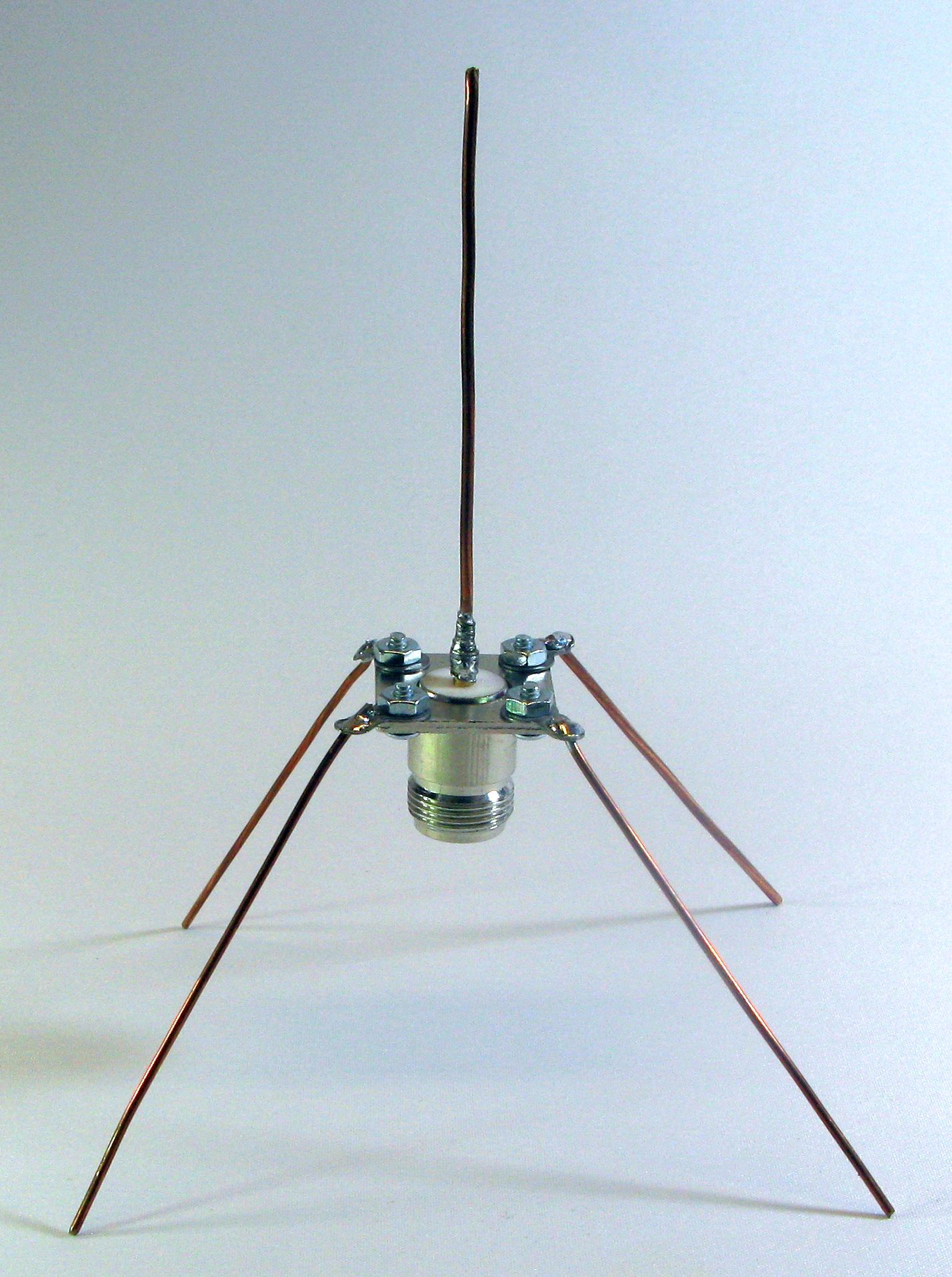

 )? Today I have built a new version with 92mm radials, however I have yet to compare (It takes some time, I see different RSSI and SNR depending on time, so I have to collect data to average them).
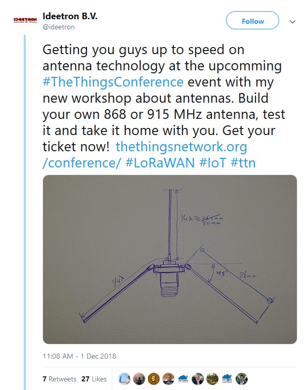
 By the way, it has two HDD magnets on bottom side… Thanks for appreciating and thanks a million for sharing antenna plans.