What sub-band/channels/frequencies does a node configured for AU915 transmit on?

I have taken the information from https://lora-alliance.org/sites/default/files/2018-05/lorawan_regional_parameters_v1_0-20161012_1397_1.pdf for AU915 and created the following table of sub-bands, channels, frequencies (uplink/downlink), etc

Sub-band Channel Freq mHz Modulation Spread factor Bandwith kHz Coding rate

1 Uplink 1 0 915.2 LoRa SF7-SF10 125 DR0-DR3 4/5
Uplink 2 1 915.4 LoRa SF7-SF10 125 DR0-DR3 4/5
Uplink 3 2 915.6 LoRa SF7-SF10 125 DR0-DR3 4/5
Uplink 4 3 915.8 LoRa SF7-SF10 125 DR0-DR3 4/5
Uplink 5 4 916.0 LoRa SF7-SF10 125 DR0-DR3 4/5
Uplink 6 5 916.2 LoRa SF7-SF10 125 DR0-DR3 4/5
Uplink 7 6 916.4 LoRa SF7-SF10 125 DR0-DR3 4/5
Uplink 8 7 916.6 LoRa SF7-SF10 125 DR0-DR3 4/5

2 Uplink 9 8 916.8 LoRa SF7-SF10 125 DR0-DR3 4/5
Uplink 10 9 917.0 LoRa SF7-SF10 125 DR0-DR3 4/5
Uplink 11 10 917.2 LoRa SF7-SF10 125 DR0-DR3 4/5
Uplink 12 11 917.4 LoRa SF7-SF10 125 DR0-DR3 4/5
Uplink 13 12 917.6 LoRa SF7-SF10 125 DR0-DR3 4/5
Uplink 14 13 917.8 LoRa SF7-SF10 125 DR0-DR3 4/5
Uplink 15 14 918.0 LoRa SF7-SF10 125 DR0-DR3 4/5
Uplink 16 15 918.2 LoRa SF7-SF10 125 DR0-DR3 4/5

3 Uplink 17 16 918.4 LoRa SF7-SF10 125 DR0-DR3 4/5
Uplink 18 17 918.6 LoRa SF7-SF10 125 DR0-DR3 4/5
Uplink 19 18 918.8 LoRa SF7-SF10 125 DR0-DR3 4/5
Uplink 20 19 919.0 LoRa SF7-SF10 125 DR0-DR3 4/5
Uplink 21 20 919.2 LoRa SF7-SF10 125 DR0-DR3 4/5
Uplink 22 21 919.4 LoRa SF7-SF10 125 DR0-DR3 4/5
Uplink 23 22 919.6 LoRa SF7-SF10 125 DR0-DR3 4/5
Uplink 24 23 919.8 LoRa SF7-SF10 125 DR0-DR3 4/5

3 Uplink 25 24 920.0 LoRa SF7-SF10 125 DR0-DR3 4/5
Uplink 26 25 920.2 LoRa SF7-SF10 125 DR0-DR3 4/5
Uplink 27 26 920.4 LoRa SF7-SF10 125 DR0-DR3 4/5
Uplink 28 27 920.6 LoRa SF7-SF10 125 DR0-DR3 4/5
Uplink 29 28 920.8 LoRa SF7-SF10 125 DR0-DR3 4/5
Uplink 30 29 921.0 LoRa SF7-SF10 125 DR0-DR3 4/5
Uplink 31 30 921.2 LoRa SF7-SF10 125 DR0-DR3 4/5
Uplink 32 31 921.4 LoRa SF7-SF10 125 DR0-DR3 4/5

4 Uplink 33 32 921.6 LoRa SF7-SF10 125 DR0-DR3 4/5
Uplink 34 33 921.8 LoRa SF7-SF10 125 DR0-DR3 4/5
Uplink 35 34 922.0 LoRa SF7-SF10 125 DR0-DR3 4/5
Uplink 36 35 922.2 LoRa SF7-SF10 125 DR0-DR3 4/5
Uplink 37 36 922.4 LoRa SF7-SF10 125 DR0-DR3 4/5
Uplink 38 37 922.6 LoRa SF7-SF10 125 DR0-DR3 4/5
Uplink 39 38 922.8 LoRa SF7-SF10 125 DR0-DR3 4/5
Uplink 40 39 923.0 LoRa SF7-SF10 125 DR0-DR3 4/5

5 Uplink 41 40 923.2 LoRa SF7-SF10 125 DR0-DR3 4/5
Uplink 42 41 923.4 LoRa SF7-SF10 125 DR0-DR3 4/5
Uplink 43 42 923.6 LoRa SF7-SF10 125 DR0-DR3 4/5
Uplink 44 43 923.8 LoRa SF7-SF10 125 DR0-DR3 4/5
Uplink 45 44 924.0 LoRa SF7-SF10 125 DR0-DR3 4/5
Uplink 46 45 924.2 LoRa SF7-SF10 125 DR0-DR3 4/5
Uplink 47 46 924.4 LoRa SF7-SF10 125 DR0-DR3 4/5
Uplink 48 47 924.6 LoRa SF7-SF10 125 DR0-DR3 4/5

6 Uplink 49 48 924.8 LoRa SF7-SF10 125 DR0-DR3 4/5
Uplink 50 49 925.0 LoRa SF7-SF10 125 DR0-DR3 4/5
Uplink 51 50 925.2 LoRa SF7-SF10 125 DR0-DR3 4/5
Uplink 52 51 925.4 LoRa SF7-SF10 125 DR0-DR3 4/5
Uplink 53 52 925.6 LoRa SF7-SF10 125 DR0-DR3 4/5
Uplink 54 53 925.8 LoRa SF7-SF10 125 DR0-DR3 4/5
Uplink 55 54 926.0 LoRa SF7-SF10 125 DR0-DR3 4/5
Uplink 56 55 926.2 LoRa SF7-SF10 125 DR0-DR3 4/5

7 Uplink 57 56 926.4 LoRa SF7-SF10 125 DR0-DR3 4/5
Uplink 58 57 926.6 LoRa SF7-SF10 125 DR0-DR3 4/5
Uplink 59 58 926.8 LoRa SF7-SF10 125 DR0-DR3 4/5
Uplink 60 59 927.0 LoRa SF7-SF10 125 DR0-DR3 4/5
Uplink 61 60 927.2 LoRa SF7-SF10 125 DR0-DR3 4/5
Uplink 62 61 927.4 LoRa SF7-SF10 125 DR0-DR3 4/5
Uplink 63 62 927.6 LoRa SF7-SF10 125 DR0-DR3 4/5
Uplink 64 63 927.8 LoRa SF7-SF10 125 DR0-DR3 4/5
+
Uplink 1 64 915.9 LoRa SF8 500 DR4
Uplink 2 65 917.5 LoRa SF8 500 DR4
Uplink 3 66 919.1 LoRa SF8 500 DR4
Uplink 4 67 920.7 LoRa SF8 500 DR4
Uplink 5 68 922.3 LoRa SF8 500 DR4
Uplink 6 69 923.9 LoRa SF8 500 DR4
Uplink 7 70 925.5 LoRa SF8 500 DR4
Uplink 8 71 927.1 LoRa SF8 500 DR4

Downlink	1	0	923.3	LoRa	SF7-SF12	500	DR8-DR13	
Downlink	2	1	923.9	LoRa	SF7-SF12	500	DR8-DR13	
Downlink	3	2	924.5	LoRa	SF7-SF12	500	DR8-DR13	
Downlink	4	3	925.1	LoRa	SF7-SF12	500	DR8-DR13	
Downlink	5	4	925.7	LoRa	SF7-SF12	500	DR8-DR13	
Downlink	6	5	926.3	LoRa	SF7-SF12	500	DR8-DR13	
Downlink	7	6	926.9	LoRa	SF7-SF12	500	DR8-DR13	
Downlink	8	7	927.5	LoRa	SF7-SF12	500	DR8-DR13	

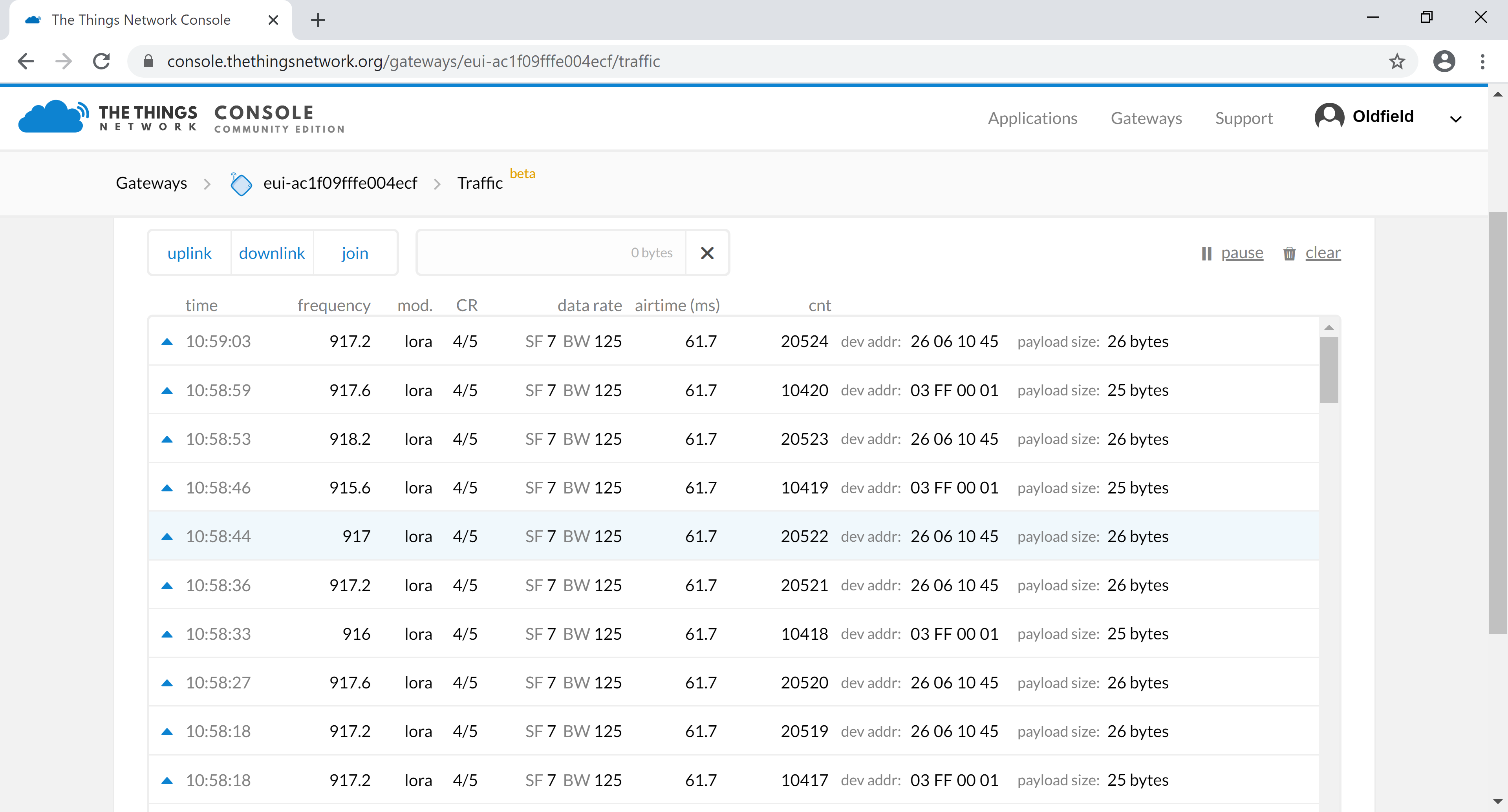
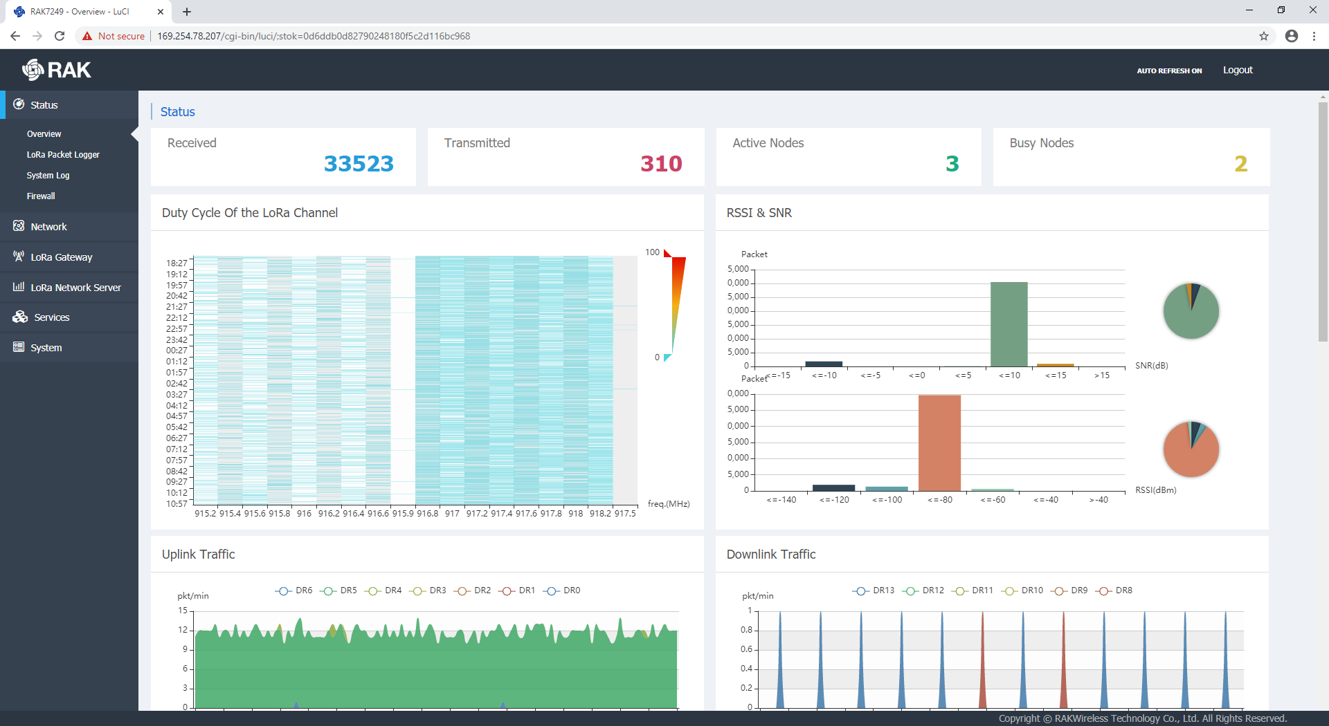
As I understand it, a gateway can be 1 channel, but TTN requires 8 channels min for a gateway. I have a 16 channel RAK gateway.

What I’m trying to understand, please help me -

If I have a node configured for AU915 (eg RAK Wisnode), does the node cycle through all 64 channels sending out a payload, eg “Hello, world!”?

Thank you.

The frequencies a TTN gateway should support for AU915 are given here:

https://www.thethingsnetwork.org/docs/lorawan/frequency-plans.html

If your gateway has an additional concentrator card you could configure it to any other sub-band, but it’s not entirely clear if there will be a practical way to use that - you’d need to get your nodes using additional frequencies other than the ones TTN would tell them to use. And it’s unclear what the TTN servers would do if presented with an uplink on a frequency from a different sub-band - correctly calculate the corresponding downlink frequency? Drop it? Do something incorrect?

There’s also the question of how uplink-downlink timing works in a two concentrator system.

Realistically for TTN you might as well pull the second concentrator out and hang it on a raspberry pi (or better yet one of the eMMC models of OrangePi) and have yourself another gateway to put in another location. TTN and other basic LoRaWAN networks benefit far more from having lots of budget 8 channel gateways spread around, they aren’t really able to use 16 channel ones to any greater advantage. Even a private network would find it difficult: unless all the gateways were 16 channel you’d have to dynamically figure out when a node was near a 16 channel gateway and suggest it start using the extra subband.

Semtech’s recommendation for multi-subband regions is indeed that a node with no information about the network it would interact with should cycle through all of the subbands until it gets a response.

But for sake of efficiency, most people modify their firmware to try only the subband TTN actually uses.

1 Like

Cslorabox, very clear, very helpful. Thank you. Regards.

I just thought I’d follow up with where I’ve got to. My 16 channel gateway (RAK4297) is working perfectly. I had a problem getting the second concentrator to go, however, with RAKwireless’s help, that has been sorted.

I have three nodes operating. one is RAK7204 temp/humidity sensor. It appears to be working on AU915 sub-band 2 (channels 8-15) … and going well. The other two are simple Dragino shields on Arduino UNOs. One is operating on AU915 sub-band 2 (channels 8-15) while the other one is operating on AU915 sub-bands 1 &2 (channels 0-15).

You can see the frequencies (and therefore channels) from the screen-shot below of the gateway traffic.

image

There is one slight issue here. The gateway is not showing the 7204 traffic for some reason. I’m yet to sort that out. However, you can see that traffic from inside the application and device.

The other screen-shot -

image

shows the duty cycle. You can clearly see that traffic through the gateway to TTN is covering channels 0-15 which I absolutely understand is contrary to the TTN “rules”, however, the TTN appears to be handling it in the normal way.

The difference in the amount of blue in the two sub-bands is due to one node operating on 0-7 and 2 nodes operating 8-15 (assuming that 7204 is not included since it doesn’t appear in the TTN gateway console).

This is the code I’m running on both Dragino nodes. You can see the references in the header -

/******************************* NODE 2 Hello, Ryan! ***********************************
Thomas Laurenson AU915

Documentation -

https://www.thomaslaurenson.com/blog/2018/07/21/dragino-lorashield-on-AU915-using-arduino-lmic-library/

Example sketch -

https://github.com/thomaslaurenson/arduino-lmic/blob/master/examples/ttn-abp-dragino-lorashield-au915/ttn-abp-dragino-lorashield-au915.ino

https://github.com/thomaslaurenson/Dragino_LoRaShield_Node_AU915 go to Examples

https://github.com/thomaslaurenson/Dragino_LoRaShield_Node_AU915/tree/master/examples/Dragino_LoRaShield_AU915

Modified by Thomas Laurenson, 2017
Specific modifications for use of Dragino LoRaSHield on AU915, sub-band 2

Copyright © 2015 Thomas Telkamp and Matthijs Kooijman

Permission is hereby granted, free of charge, to anyone
obtaining a copy of this document and accompanying files,
to do whatever they want with them without any restriction,
including, but not limited to, copying, modification and redistribution.
NO WARRANTY OF ANY KIND IS PROVIDED.

This example sends a valid LoRaWAN packet with payload “Hello,
world!”, using frequency and encryption settings matching those of
the (early prototype version of) The Things Network.

Note: LoRaWAN per sub-band duty-cycle limitation is enforced (1% in g1,
0.1% in g2).

Change DEVADDR to a unique address!
See http://thethingsnetwork.org/wiki/AddressSpace

Do not forget to define the radio type correctly in config.h.

*******************************************************************************/

#include <lmic.h>
#include <hal/hal.h>
#include <SPI.h>

// LoRaWAN NwkSKey, network session key
// This is the default Semtech key, which is used by the prototype TTN
// network initially.
static const PROGMEM u1_t NWKSKEY[16] = { 0x2B, 0x7E, 0x15, 0x16, 0x28, 0xAE, 0xD2, 0xA6, 0xAB, 0xF7, 0x15, 0x88, 0x09, 0xCF, 0x4F, 0x3C };

// LoRaWAN AppSKey, application session key
// This is the default Semtech key, which is used by the prototype TTN
// network initially.
static const u1_t PROGMEM APPSKEY[16] = { 0x2B, 0x7E, 0x15, 0x16, 0x28, 0xAE, 0xD2, 0xA6, 0xAB, 0xF7, 0x15, 0x88, 0x09, 0xCF, 0x4F, 0x3C };

// LoRaWAN end-device address (DevAddr)
// See http://thethingsnetwork.org/wiki/AddressSpace
static const u4_t DEVADDR = 0x03FF0001 ; // <-- Change this address for every node!

// These callbacks are only used in over-the-air activation, so they are
// left empty here (we cannot leave them out completely unless
// DISABLE_JOIN is set in config.h, otherwise the linker will complain).
void os_getArtEui (u1_t* buf) { }
void os_getDevEui (u1_t* buf) { }
void os_getDevKey (u1_t* buf) { }

static uint8_t mydata[] = “Hello, Ryan!”;
static osjob_t sendjob;

// Schedule TX every this many seconds (might become longer due to duty
// cycle limitations).
const unsigned TX_INTERVAL = 10;

// Pin mapping
const lmic_pinmap lmic_pins = {
.nss = 10,
.rxtx = LMIC_UNUSED_PIN,
.rst = 9,
.dio = {2, 6, 7},
};

void onEvent (ev_t ev) {
Serial.print(os_getTime());
Serial.print(": ");
switch (ev) {
case EV_SCAN_TIMEOUT:
Serial.println(F(“EV_SCAN_TIMEOUT”));
break;
case EV_BEACON_FOUND:
Serial.println(F(“EV_BEACON_FOUND”));
break;
case EV_BEACON_MISSED:
Serial.println(F(“EV_BEACON_MISSED”));
break;
case EV_BEACON_TRACKED:
Serial.println(F(“EV_BEACON_TRACKED”));
break;
case EV_JOINING:
Serial.println(F(“EV_JOINING”));
break;
case EV_JOINED:
Serial.println(F(“EV_JOINED”));
break;
case EV_RFU1:
Serial.println(F(“EV_RFU1”));
break;
case EV_JOIN_FAILED:
Serial.println(F(“EV_JOIN_FAILED”));
break;
case EV_REJOIN_FAILED:
Serial.println(F(“EV_REJOIN_FAILED”));
break;
break;
case EV_TXCOMPLETE:
Serial.println(F(“EV_TXCOMPLETE (includes waiting for RX windows)”));
if (LMIC.dataLen) {
// data received in rx slot after tx
Serial.print(F("Data Received: "));
Serial.write(LMIC.frame + LMIC.dataBeg, LMIC.dataLen);
Serial.println();
}
// Schedule next transmission
os_setTimedCallback(&sendjob, os_getTime() + sec2osticks(TX_INTERVAL), do_send);
break;
case EV_LOST_TSYNC:
Serial.println(F(“EV_LOST_TSYNC”));
break;
case EV_RESET:
Serial.println(F(“EV_RESET”));
break;
case EV_RXCOMPLETE:
// data received in ping slot
Serial.println(F(“EV_RXCOMPLETE”));
break;
case EV_LINK_DEAD:
Serial.println(F(“EV_LINK_DEAD”));
break;
case EV_LINK_ALIVE:
Serial.println(F(“EV_LINK_ALIVE”));
break;
default:
Serial.println(F(“Unknown event”));
break;
}
}

void do_send(osjob_t* j) {
// Check if there is not a current TX/RX job running
if (LMIC.opmode & OP_TXRXPEND) {
//Serial.println(F(“OP_TXRXPEND, not sending”));
Serial.print("OP_TXRXPEND, not sending; at freq: ");
Serial.println(LMIC.freq);
} else {
// Prepare upstream data transmission at the next possible time.
LMIC_setTxData2(1, mydata, sizeof(mydata) - 1, 0);
Serial.print(F("Packet queued for freq: "));
Serial.println(LMIC.freq);
}
// Next TX is scheduled after TX_COMPLETE event.
}

void setup() {
Serial.begin(9600);
Serial.println(F(“Starting”));

#ifdef VCC_ENABLE
// For Pinoccio Scout boards
pinMode(VCC_ENABLE, OUTPUT);
digitalWrite(VCC_ENABLE, HIGH);
delay(1000);
#endif

// LMIC init
os_init();
// Reset the MAC state. Session and pending data transfers will be discarded.
LMIC_reset();

// Set static session parameters. Instead of dynamically establishing a session
// by joining the network, precomputed session parameters are be provided.
#ifdef PROGMEM
// On AVR, these values are stored in flash and only copied to RAM
// once. Copy them to a temporary buffer here, LMIC_setSession will
// copy them into a buffer of its own again.
uint8_t appskey[sizeof(APPSKEY)];
uint8_t nwkskey[sizeof(NWKSKEY)];
memcpy_P(appskey, APPSKEY, sizeof(APPSKEY));
memcpy_P(nwkskey, NWKSKEY, sizeof(NWKSKEY));
LMIC_setSession (0x1, DEVADDR, nwkskey, appskey);
#else
// If not running an AVR with PROGMEM, just use the arrays directly
LMIC_setSession (0x1, DEVADDR, NWKSKEY, APPSKEY);
#endif

// THIS IS WHERE THE AUSTRALIA FREQUENCY MAGIC HAPPENS!
// The frequency plan is hard-coded
// But the band (or selected 8 channels) is configured here!
// This is the same AU915 band as used by TTN

// First, disable channels 0-7
// for (int channel=0; channel<8; ++channel)
// {
// LMIC_disableChannel(channel);
// }

// Second, disable channels 16-72 (is there 72 ??)
for (int channel = 16; channel < 72; ++channel)
{
LMIC_disableChannel(channel);
}
// This means channels 8-15 are up
// this means channels 0-15 are up in this revised Node-2
// Disable link check validation
LMIC_setLinkCheckMode(0);

// Set data rate and transmit power (note: txpow seems to be ignored by the library)
LMIC_setDrTxpow(DR_SF7, 14);

// Start job
do_send(&sendjob);
}

void loop() {
os_runloop_once();
}

The interesting bit occurs at line 194. I have used this to turn-on and turn-off channels to test the TTN response.

Thanks again for your help. Regards