I had a look at how logic level converters work (never heard of them before) and as I understand it, you need e.g. a 5 V and a 3.3 V reference voltage. How do I do this with my 4.2 V battery as the only power source?
1- use a 3v3 arduino and 3v3 sensors
you only need to convert your lipo voltage to 3v3 and you don’t need a level converter for I/O
you can use something like this (called buckboost)
-https://www.ebay.com/itm/2in1-Buck-Boost-0-8-6V-to-3-3V-DC-DC-Converter-Module-for-esp8266-Wifi-Bluetooth-/272426902863
you find many of these boards- step down step up buckboost ect
input from 0.8 to 6 v -> output steady 3v3
so if you drain your battery to say 2.6 v… the output is still 3v3 and your arduino still works.
if you connect your fully charged battery @ 4.2 v also the output is 3v3 no problemo
2- use a 5v arduino and 5v sensors
use 5v I/O sensors and you don’t need a level converter
you need a so called boost module to make the 5v from the lipo
best is then to choose a combination of dc dc boost converter and lipo charger.
example
now you can leave your lipo attached to the device and plug in an adapter to charge
3- a mix… 5v arduino and 3v sensors / 3v3 arduino and 5v sensors
then you make it yourself difficult 
add an extra dc dc converter from 5v to 3v3 so you have the 2 voltages needed for the levelconverter board
* I didn’t search for the cheapest dc dc ect. also depends on the capacity they can deliver
… however, this way the issue with the LoRa module remains, unless using the one I mentioned (that already include converters). To be safe, two logic level converters like this one are needed for the LoRa module (though maybe just one is sufficient for the inputs - I do not remember the number needed).
There are too many variables. Willing to use a LiPo, I would buy a LoRa32U4 that has everything inside, including LiPo charger, is 3.3, etc. And cheap.
Thanks for your input. I found in the past that the electromagnetic waves emitted by the coils on buck-boost converters could interfere with my HX711, as well as with LoRa.
Having done some research, I now consider using a HT7333 regulator instead, as described e.g. here:
I was coming there in point 3… your to fast ![]()
And indeed the easiest setup is a complete board with all the components.
it’s nice to leave your device on while charging for example, but also think of lipo protection against overcharging ect.
a led indication on the board when your lipo is fully charged… little things, but also depends on the use case.
Sounds good! ![]()
You asked about using your 5V arduinos with a LoRa device, so clearly the 5V supply is available and presumably the 3.3V also.
Never tried logic level converters where one side is 4.2V and the other is 3.3V, its just so much easier these days to power everything from a 3.3V supply.
I have very good experience with ESP32 LoRa module and Feather 32u4 LoRa - if you need CPU power and complicated calculations ESP32 is the way to go - fir low power consumption Feather 32u4 is a lot better - prices are about £15 for both modules in aliexpress
Hey guys!, could someone help me?
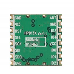
What is the communication protocol that HPD13A uses to communicate with arduino? I’m kind of confused as this has a SEL PIN … 
Thanks in advance!

Looks like the same pin layout as an RFM95 to me, so its SPI
Yes!! you were right,
I was testing again and figured it out this morning, I’m not sure if this is obvious for someone who already works with other LoRa modules, I was completely confused about it.
Well after some research and comparisons done I decided to make an schematic for this module connected to Arduino, base in this example https://github.com/sandeepmistry/arduino-LoRa
#My apologies, made a bad a diagram, in my real modules I have the antenna, but not in the diagram
#Also is necessary the proper power supply for the system (3.3V)
Cheers
HPD13A connected to Arduino
MODERATOR NOTE: do NOT use this diagram to create your node if you are running the UNO at 5V (normal operating mode), it connects 3.3 volt pins to 5 volt which will damage the LoRa module. Also the mandatory antenna is missing which will result in damage to the module as well.
Are the I/O pins of this module 5V tolerant? If not specified as such you are going to destroy the module by connecting it directly to Uno I/O pins.
Use level conversion…
Hey Kersing!
Well, I haven’t tried them with 5V directly, but I connected them to the 3.3V pins from the arduinos and then programmed the Sender and Receiver example from the link above and it worked, the HPD13A modules didn’t get hot at all.
#_ _
what is your opinion?, in the past I tried using SIM800L modules (gsm), and the voltage was a big problem and I’ve got to use a couple of bateries, but in this case anything happened.
Unless you are 100% certain the HPD13A is a 5V tolerant device, I would remove that connection diagram.
Anyone finding the diagram might assume, that since its posted on the TTN forum, its an accurate and safe way to connect the HPD13A.
A lot of UNOs can be limited to 50mA on the 3.3V supply pin, not enough for a LoRa device, so using the UNO 3.3V supply will likley lead to unstable\unreliable operation.
Additionally, the ‘diagram’ shows no antenna connection, operating it without an antenna is another way to destroy a LoRa device.
And the quote from the Github repository you used to formulate the diagram;
“If your Arduino board operates at 5V, like the Arduino Uno, Leonardo or Mega, you will need to use a level converter for the wiring to the Semtech SX127x module. Most Semtech SX127x breakout boards do not have logic level converters built-in”
I’ve added a note to the message to warn anyone stumbling across the message.
You are mistaken. You are trying them with 5V directly. May-be not the power connection, but you have connected all input pins to 5V because the Uno drives them to 5V when the output level is high.


