Whisper Node and RFM95 DIOs

Hello,

I’ve been playing with my Whisper Node this week and it seems to be working fine for raw LoRa (using RadioHead RF95 library), but when using the LMIC it sends only the first message to the LoRaWAN Gateway and kind of hangs after that.

I was wondering if that’s related to the RFM95 DIOs not being connected to the MCU? Here the documentation, looks like only the DIO0 is connected to the ATMega328p INT0, but the others RFM95 DIOs are not connected…

(source: https://bitbucket.org/talk2/whisper-node-avr-lora)

I’m about to solder a jumper there to connect the DIO1 (as far I understood I don’t need the DIO2), but would like to confirm with other users first as I’m not very good at soldering :thinking:

Thank you,
MO

Just an update on this. I’ve manage to solder the jumper (JP15) and it worked! I need to confess was my first SMD soldering work and it wasn’t difficult at all.

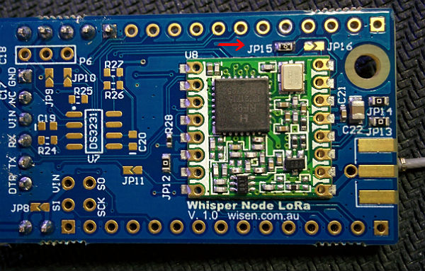
Whisper Node with JP15, connecting the RFM95 DIO1 to the MCU A2

Here how my pin mapping looks like now:

// Pin mapping
const lmic_pinmap lmic_pins = {
  .nss = 10,
  .rxtx = LMIC_UNUSED_PIN,
  .rst = 7,
  .dio = {2, A2, LMIC_UNUSED_PIN},
};

Good day would you be able to share your entire sketch for the Whisper Node?

I’m NOT a very gifted coder, so i’m trying to get mine up and running, having a hard time finding a good example sketch

1 Like

Thank you @MoebiusL for sharing the required hardware change. This was my first SMD soldering too, but it was not too hard to do. As illustrated in your picture I took one of the Zero-ohm-links supplied with the nodes (a white strip of about 5) and soldered it over the two JP15 pads, functionally similar to a through-hole pin jumper.

I added a bit of flux on the two adjoining pads, heated them up with the soldering iron and lightly touched each of them with 0.3 mm flux cored solder, still applying heat. I carefully placed the small jumper over both of them using a pair of pincers and applied heat to solder it in place. As I did not have a suitable SMD tip for my iron, heat spread over both pads. Actually this helped in this case as the jumper settled quite nice. Finally I measured resistance over both adjoining pads to verify they were connected. I then changed the pin mapping for lmic.

My Whisper Nodes have been posting data to TTN for a few days now, and it seems to have resolved the issue in a reliable manner. I assume this was by design and part of the reason why the jumpers are supplied. So far I love these nodes and I think they are perfect for low energy applications.

I have one related question - if I want to change the u.FL connector for a SMA edge connector, do I have to desolder the u.FL connector? I assume I do, but I would like confirmation from someone who knows @wisen .

1 Like

Hi @eivholt, I’ve soldered the SMA connector on the board without removing the u.FL. It sits perfectly there… I just had to put my soldering iron to high temperature as the SMA seems o absorb all heat making very difficult for the solder to melt nicely.

Btw, I’m also having fun with my nodes, but I keep moving them from one project to another… might need a few more.

Cool, I’ll try leaving it on. I assume the u.FL doesn’t form a closed circuit as long as no antenna is connected to it. I can imagine the SMA absorbs a lot of heat. I don’t have a broad tip for my soldering iron so thanks for the heads up!

I am going to add a coin cell battery holder on some of my Whisper Nodes and see how it works out.

It does not.

I would leave it in place. Unless you have a lot of de-soldering experience, there is a significant risk of damaging the board in the removal attempt.

Hi eivholt,

Just to confirm that it’s not necessary to desolder the u.FL connector. The SMA Edge will fit without creating any short.

In case anyone needs to desolder an u.FL or SMA, the best way is by using hot-air. Alternatively carefully destroying the component with a wire cutter and desoldering individual “legs” is the safest approach.

Thanks for the confirmation. I have done this successfully on two nodes so far. Is it possible to give any general comparison on using the supplied pcb-antenna as apposed to the SMA whip antenna with respect to energy consumption. This is probably a many faceted problem to answer but taken the scenario: I have my lora gateway (TTN GW) in my house and I want nodes no further than 15 meters from this point. I want my nodes to run on 3V coin cells. Are these two antennas even anything I should consider when optimizing energy consumption? I take it a “larger” antenna requires more energy to resonate, but at what order of magnitude? Downlink is not in use in this example. Snowy and wet scandinavian weather is a consideration as the antenna will be exposed.
I would appreciate any insight that could help me make the nodes last as long as possible. I am awaiting an oscilloscope and will perform some tests with the different antenna configurations but I suspect someone with deeper knowledge has already done this.

Its the opposite.

In general, the larger the antenna, the better it radiates, and thus you require less transmit power (and less battery current) to cover a given distance.

Those small ceramic antennas are not very efficient, compared say to a simple bit of wire, although the wire would be bigger of course.

You need to be careful with coin cells, you may find their voltage drops, perhaps significantly, when the node is transmitting. A scope is useful for checking this, a multimeter may not capture the change for short duration packets…

2 Likes

Thanks for your posts @MoebiusL, @eivholt. Great to hear it works, I’m interested in this configuration too.

Were you using the RocketScream low power library? Some have had trouble with the combination: http://talk2forum.wisen.com.au/viewtopic.php?f=4&t=93&p=366#p366

Also, I’m interested in such a setup: lmic+whispernode+lowpowerlib on ttn. Anybody here who has acompished this (and likes to share)? Thanks!

Hi,
Im i got a lora whisper node but i cant seem to find a example of how to send and receive information to the lora nertwork.

Can anyone help me?
Thanks in advance

typical friday afternoon post imho … I will be following this :wink:

expect a lot off copy/paste code

Its supposed to be powered by an ATMEGA328P and is ‘Arduino compatible’ so as long as you adjust the pin numbers to match any code for the Arduino UNO ought to work.

A Google search on ‘Arduino TTN node’ ought to find something.

Hi,

I searched and found some examples.
I manage to make one compile and run in the whisper node but i didn’t got anything on the TTN console.
The output in the serial didn’t show any errors and it was:

Starting
RXMODE_RSSI
230: engineUpdate, opmode=0x808
259: Uplink data pending
298: Airtime available at 258 (channel duty limit)
464: Ready for uplink
1034: TXMODE, freq=920000000, len=27, SF=7, BW=125, CR=4/5, IH=0
Packet queued
5158: irq: dio: 0x0 flags: 0x8
5196: Scheduled job 0x285, cb 0x3f0 ASAP
5235: Running job 0x285, cb 0x3f0, deadline 0
5450: Scheduled job 0x285, cb 0x418 at 67555
67557: Running job 0x285, cb 0x418, deadline 67555
67683: RXMODE_SINGLE, freq=923300000, SF=7, BW=500, CR=4/5, IH=0

I checked and everything looks ok, but im not that shur about the pins, the configuration for the pins i use was:

// Pin mapping
const lmic_pinmap lmic_pins = {
  .nss = 10,
  .rxtx = LMIC_UNUSED_PIN,
  .rst = 7,
  .dio = {2, A2, LMIC_UNUSED_PIN},
};

Are they ok? In the beginning of the post you mention you need to solder one of the jumpers, do i need to do it?
Any sugestions?
Thanks in advance

1 Like

did you solder that jumper

Hi,
I just soldered the header pins.
I didnt solder any jumper.
Shouln’t ir work withaut the jumper?
Thanks inglês advance

try solder jp15

Hi,

Soldering that small thing wasn’t easy, i ended up making a bridge with solder. (its the same thing i quess)
Clearly it made a diference since i see in the serial monitor the node trying to send something:

5301482: Running job 0x266, cb 0x14d0, deadline 5301481
5301537: engineUpdate, opmode=0x908
5301634: Uplink data pending
5301788: Airtime available at 5301633 (channel duty limit)
5302101: Ready for uplink
5302693: TXMODE, freq=921400000, len=27, SF=7, BW=125, CR=4/5, IH=0
Packet queued
5306817: irq: dio: 0x0 flags: 0x8
5306858: Scheduled job 0x285, cb 0x3f0 ASAP
5306902: Running job 0x285, cb 0x3f0, deadline 0
5307159: Scheduled job 0x285, cb 0x418 at 5369214
5369216: Running job 0x285, cb 0x418, deadline 5369214
5369342: RXMODE_SINGLE, freq=927500000, SF=7, BW=500, CR=4/5, IH=0
5369293: irq: dio: 0x1 flags: 0x80
5369484: Scheduled job 0x285, cb 0x8f1 ASAP
5369713: Running job 0x285, cb 0x8f1, deadline 0
5369974: Scheduled job 0x285, cb 0x449 at 5432074
5432076: Running job 0x285, cb 0x449, deadline 5432074
5432202: RXMODE_SINGLE, freq=923300000, SF=9, BW=125, CR=4/5, IH=0
5433245: irq: dio: 0x1 flags: 0x80
5433288: Scheduled job 0x285, cb 0x908 ASAP
5433331: Running job 0x285, cb 0x908, deadline 0
5433592: EV_TXCOMPLETE (includes waiting for RX windows)
5433900: Scheduled job 0x266, cb 0x14d0 at 6058897
5434169: engineUpdate, opmode=0x900

The thing is i still didn’t get anything in in TTN console.
Any ideas of the problem?

Thanks in advance