Hello,
I’ trying to reproduce the setup described in the README.md doc file of LMIC-Node (§8.1 Serial Monitor: i.e. an RPI Pico with an RFM9x Radio module).
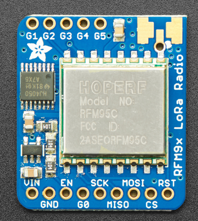
Looking at file bsf_pico.h I can see that 2 wires are needed from Pico GPIO 9 <-> DIO0 (of Lora Module), and from
Pico GPIO 10 <-> DIO1 (of Lora Module)
However, if I look at the pinout description of the LoRa Radio https://learn.adafruit.com/adafruit-rfm69hcw-and-rfm96-rfm95-rfm98-lora-packet-padio-breakouts/pinouts
I can not identify DIO0, or DIO1.
On the Radio Module the connections labelled EN (Enable) and G0 (GPIO0 - IRQ) are still free.
For this reason I assume that the connections should be:
Pico GPIO 9 <-> G0 (of Lora Module), and from
Pico GPIO 10 <-> EN
I will be extremly grateful to you, if you could confirm me this.
Thank you in advance. Cheers
Can you post a picture of the RFM module - the collection I have all have the DIO pins very clearly marked and no EN or G markings. And I have other SX1276 boards will all sorts of markings so it would be good to be sure about the identity of the board you have.
EN would imply enable which is not what the DIO1 pin needs to do - it communicates back the RxTimeout as you discovered with your Adafruit Feather.
Nope, that the enable pin for the Adafruit boards on board AP2112K regulator, see the schematic below, you get to it by clicking on ‘Downloads’ link on the page you (almost) provided a link too;
And also on the schematic you can see G0 (DIO0) is next to EN and it should be clear where DIO1 is.
The link went to http://pinout which I misread as meaning to go to http://pinout.xyz which is the RPi site for the Pi pins hence my asking for a picture. I’ve edited in the URL in the original post.
I’m trying to use an RPI Pico as end node using the LMIC Library under PlatformIO.
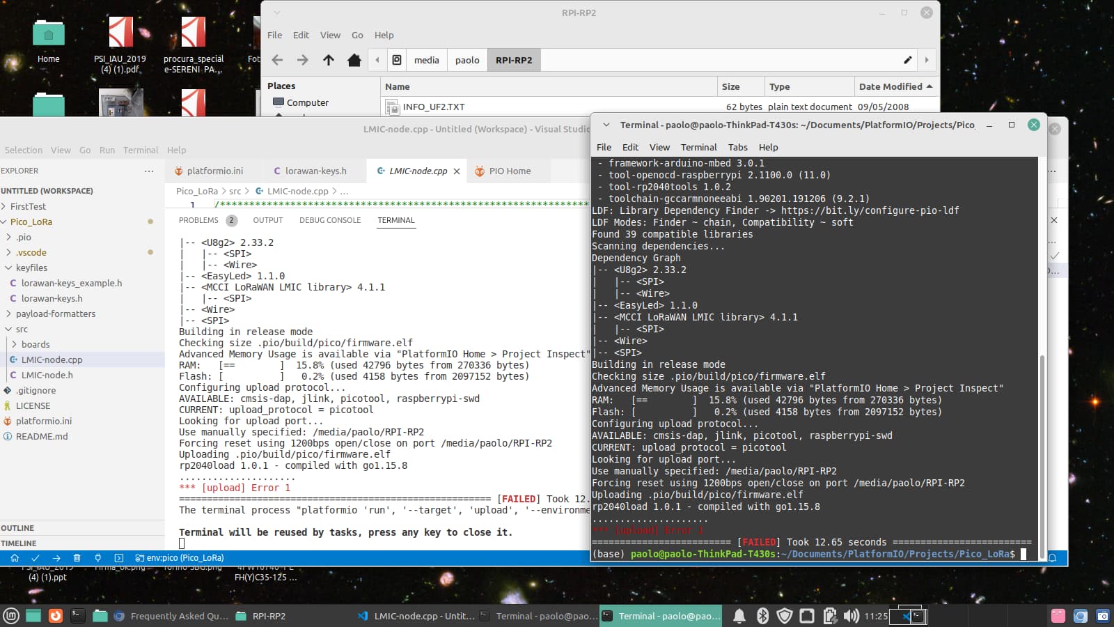
The problem is, that I can succesfully build the project on my host computer but I always get “Upload Error 1” when I try to upload the file on the RPI Pico.
Following https://docs.platformio.org/en/latest//faq.html#solution-3-run-from-terminal I also tried an upload from the command line, without any difference (screenshot attached)
I noticed, however, that the upload process is trying to upload file firmware.elf. As far as I know, I should upload file firmware.uf2 instead.
Can this explain the problem?
Have I forgot a setting anywhere? How can I modify this?
Thank you very much for any help.
Cheers.
I’ve moved this topic so we can umbrella a type of issue in to one, just in case there is anything to cross reference between them.
The .uf2 format is for drag & drop so you could do that manually.
I’ve not used the picotool upload method as I’ve repurposed a Pico as an SWD programmer, as well as having other programmers but most of my Pico programming is on a Pi 4 which also runs as a programmer. So plenty of combos to check.
The other thing is that the .elf is reporting a binary that appears to be destined to run from RAM rather than flash.
Have you got Blinky working on a Pico before you tried this?
By the way, my first experiment used a RPI 4 as host computer, but I did not manage to build the Platform IO Project.
Now I’m using a Linux Laptop and the build runs well.
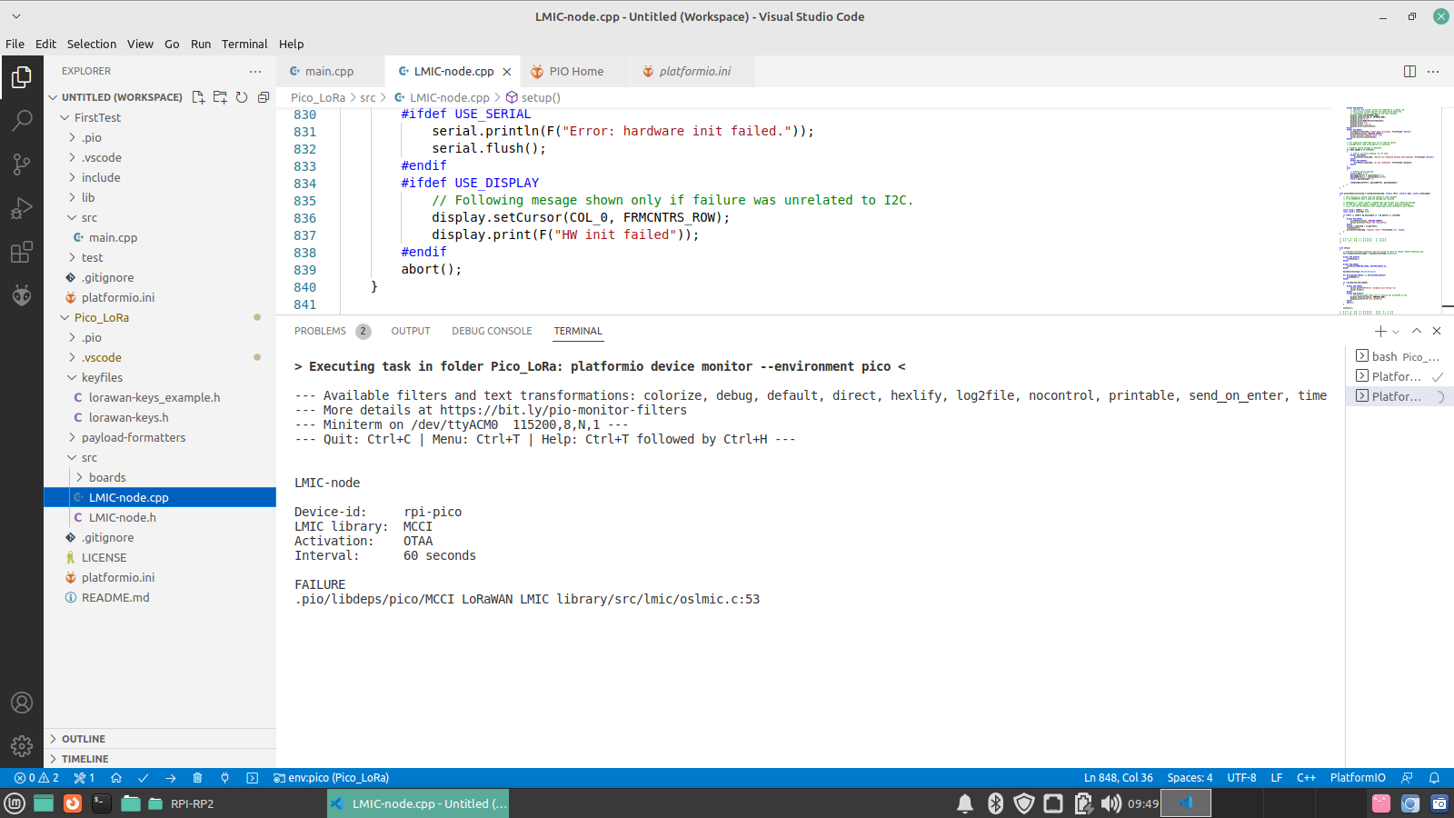
LMIC-Node test went a step further but ended with "Failed to open directory “RPI-RP2” - Error opening directory “/media/paolo/RPI-RP2”: permission denied.
No, there is a very simple RTOS in the heart of LMIC, but the function does say Initialise the OS with these pin settings so …
yes, it is saying the pins defined in the code aren’t giving a response from the radio. Usually it’s well detailed in the documentation for LMIC-node but you have control over how you connect the radio to the Pico so you have to tell the code how you have connected it.