I can’t seem to get a straight answer from Adafruit forum as to whether the Adafruit LorRa Feather has the LoRaWAN stack installed and thus can connect to a LoRaWAN gateway like the MultiTech Conduit.
What do you guys say?
I can’t seem to get a straight answer from Adafruit forum as to whether the Adafruit LorRa Feather has the LoRaWAN stack installed and thus can connect to a LoRaWAN gateway like the MultiTech Conduit.
What do you guys say?
The feather has an RFM96 module, which contains just the LoRa transceiver. You will need to run a LoRa stack on the 32u4 microcontroller yourself. Adafruit seems to only offer software for raw LoRa (not LoRaWAN to a gateway) communication, but AFAICS the IBM LMIC library (which I ported to Arduino) should run on it just fine.
Wow Matt, thanks for the info and the link to your port. I will check it out.
Thanks again for sharing your work.
I received an email from someone today that they were able to make slight modifications to the LMIC library and use it with a Feather HUZZAH (ESP8266) and my LoRa FeatherWing IOX. So that’s another option for you as well.
Dan, adding your LoRa FeatherWing to a Feather HuZ would be a great option, as one of my solutions does not need to go LoRaWAN. I am just using Feather LoRa boards and need to get the data to Azure.
Could you comment on this option.
My intent with the IOX board is that you have access to every single pin of the RFM module to allow maximum compatibility with libraries while also avoiding the I/O limitations of the ESP8266. I have example programs linked in the blog article for a beacon, a general purpose transceiver, and a gateway to Adafruit IO. You’ll see that the code is very simple and roughly based on the Ideetron Nexus library. All three example programs use the modules in LoRa mode.
Implementing the full stack using the IBM LMIC library seems to be the way to go for LoRaWAN. The person who emailed me said they successfully tested it on TTN. I asked them to post about it on this forum.
Thank you. I will start digging in.
You were right to remind me Dan 
Trying to compile the LoRaWAN stack here: https://github.com/things4u/LoRa-LMIC-1.51 for the Feather 32U4 generates an error stating 107% of storage space used. The same code does compile without errors for an arduino uno or pro-mini. Having said that, I don’t know how this code relates exactly to Matthijs’s version of the stack where size is concerned. Maybe he can shed some light on that, I’m curious too.
A solution could be using the 900 MHz Feather M0-Lora which has plenty of memory. However there are some changed needed in the compiler directives (conditional compiling) as the compiler will not recognise which .h files to include.
The Dan W’s LoRa FeatherWing IOX works on all feathers among which is the Feather Huzzah (ESP8266) with also has plenty of memory. The library from the link above runs on the Feather Huzzah with FeatherWing IOX and seems to work very well on TTN. Tested ABP (activation by personalisation) only.
The following small changes have to be made in the firmware:
In the .ino file:
lmic_pinmap pins = {
.nss = 2, // Connected to pin D
.rxtx = 2, // For placeholder only, Do not connected on RFM92/RFM95
.rst = 1, // Needed on RFM92/RFM95? (probably not) D0/GPIO16
.dio = {5, 6, 7}, // Specify pin numbers for DIO0, 1, 2
// connected to D5, D4, D3
};
In the hal.cpp file:
Adafruit_MCP23008 iox;
static void hal_io_init () {
iox.begin(); // Initialize Adafruit MCP23008 @ IIC base address
iox.pinMode(pins.nss, OUTPUT); // Adapted for MCP23008
// iox.pinMode(pins.rxtx, OUTPUT); // NOT used on ESP8266, // Adapted for MCP23008
iox.pinMode(pins.rst, OUTPUT); // Adapted for MCP23008
iox.pinMode(pins.dio[0], INPUT); // Adapted for MCP23008
iox.pinMode(pins.dio[1], INPUT); // Adapted for MCP23008
iox.pinMode(pins.dio[2], INPUT); // Adapted for MCP23008
}
3) All other references to digitalRead(pin) and
digitalWrite(pin) should be replaced by
iox.digitalRead(pin) and
iox.digitalWrite(pin) for all the DIO pins of the RFM95.
Ordering Dan’s IOX boards from www.oshpark.com took about 13 day’s from ordering to snail mail in the Netherlands, total costs about € 9,- for 3 bare PCB’s. Thanks Dan for sharing.
Outstanding work. Thanks for sharing.
AFAIU, the things4u repo took an earlier version of my port and made some changes (including, IIRC, replacing the AES library to save on space). I believe I’ve copied or reimplemented all generically useful changes made in that library (at least up to a few months ago), and added some more changes. So, I think my library would be the “most current” one to use, though I haven’t looked at the things4u one recently.
One thing to consider is that (the master branch of) my library still uses the original AES library, and might not fit comfortably in a 328p or 32u4. The “mjs” branch of my library contains (among other improvements) the Ideetron AES implementation (which I think things4u also uses) and should be smaller. However, I created that branch for a specific project with some time pressure, so it needs a bit more cleanup and testing before I push the changes to master (probably after some reordering or rebasing).
Could you expand on the changes needed? The library should be able to compile with any board that has a proper “Arduino” core, there shouldn’t be anything architecture-specific in the library (it’s been tested on an ESP, teensy and even the Intel Curie. What core does this M0 feather use? The official Arduino SAMD core that is used for the Arduino Zero? Or some other custom core?
Looking at the changes needed, it seems that core doesn’t support the standard Arduino API. Any clue why it chose not to?
Hello,
I am very interested in this thread. I am developing a product that needs to connect to the LoRaWAN and I have the Adafruit M0 w/Lora (Product 3178).
I bought this because I had read that the M0 was the only Adafruit board that had enough memory for the sketch. Now I am trying to find code to get me connected to the LoraWAN. I read above that the LoRa-LMIC-1.51 stack could work, but would need to be altered to work with the M0. Any ideas of what needs to be changed?
I have some development experience, but am completely new to Lora and LoraWAN. Any help would be appreciated. And I would be more than willing to try code on my M0 and report back successes and failures.
Sean
I believe Adafruit customizes their cores to specifically fit their boards and tutorials. It seems they geared their LoRa Feathers to support simple P2P implementations instead of full LoRaWAN.
This is one of the reasons I have continued to work on my LoRa(WAN) FeatherWings in the hopes that the completely flexible hardware is still relevant and useful, despite the availability of a “LoRa” Feather.
I support that idea. A full LoRaWAN wing to go on a simple Feather would make a nice package.
@sschearer Hi Sean, I use the Adafruit M0 proto board with the syncchannel addon (RFM95), so nearly the same setup (the integrated version was not available yet). I have a working setup. You have to deal with the DIO0, DIO1 and DIO2 pin of the RFM95 module. Only DIO0 is connected to D4 on your Adafruit board. Connect DIO1 and DIO2 to any free available data port (for instance, in my case D6 and D11). Then find the pin definition part in the LMIC code:
// Pin mapping
const lmic_pinmap lmic_pins = {
.nss = 8, // change to match cs / nss
.rxtx = LMIC_UNUSED_PIN,
.rst = LMIC_UNUSED_PIN, // possible 4 for the adafruit board
.dio = {5, 6, 11}, // DIO0, DIO1, DIO2 data pins
};
I did not use the rst pin, but as it is connected in your board to D4, you can put ‘4’ here. This works with the OTAA code (after some nights struggling with ttnctl…). But it CAN work this way! Now I have some stability problems (code will run for no longer than an hour). Compile would only work in the Arduino IDE (v1.6.7) with all updated libraries. Still work to do, on the stability issue! Cheers
I got hold of the M0 Lora feather an I got it to compile using the https://github.com/matthijskooijman/arduino-lmic/tree/non-avr-printf branch.
However it seems to hang after setup.
here is pin mapping that I am using
const lmic_pinmap lmic_pins = {
  .nss = 8,
  .rxtx = LMIC_UNUSED_PIN,      // (5) should be foreseen for later release (ok for A, needed for C)
  .rst = 4,
  .dio = {3, 1, 2},  // DIO0, DIO1, DIO2
};Hi @kgbvax, Just take a look at my previous post in answer to Sean. The needed DIO pins of the RFM95 are not all connected on the Adafruit board. It is unclear which ones really are needed, but connecting DIO0, 1 and 2 brings a good result for me. I only changed the stated lmic_pinmap statement (and some soldering). Cheers.
Hmm, at least per schematic they are connected, this is where I got the .dio settings. Perhaps I will just measure whether this is correct…
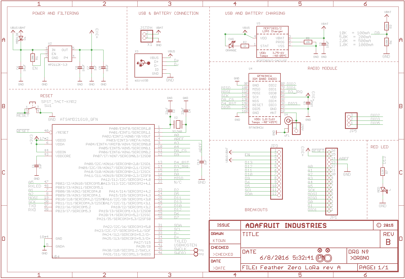
Referring to the Adafruit docs only DIO0, CS and Reset are connected:
Since not all pins can be brought out to breakouts, due to the small size of the Feather, we use these to control the radio module
#8 - used as the radio CS (chip select) pin
#3 - used as the radio GPIO0 / IRQ (interrupt request) pin.
#4 - used as the radio Reset pin
Since these are not brought out there should be no risk of using them by accident!
There are also breakouts for 3 of the RFM’s GPIO pins (IO1, IO2, IO3 and IO5). You probably wont need these for most uses of the Feather but they are available in case you need 'em!
That is why you have to connect DIO1 and DIO2 to free D pins, and fill in this ports in the lmic_pinmap statement. IF these pins where connected, to which dataport? That is not in the schematic. But measuring is ‘proof of the pudding’. Cheers
You are right; heating the soldering iron…
Note that only one of DIO1 and DIO2 is needed for LoRa communication, the other is needed for FSK mode (IIRC the README of my lmic repository states which is which). DIO0 is needed for both.