Antenna experiment - 868Mhz J-pole

After a busy weekend I finally did some antenna measurements.

The J-pole was always one of my favorites. As a student I had not much money to spend on my equipment and not much room to place an antenna so I built a J-pole for 2m to be able to reach our local repeater with my old handheld tranceiver. So when I started my LoRa developments, the J-pole immediately came up as a nice antenna. It’s small, easy to build and does not take much space (read: does not attract too much attention when mounted outdoors).

The antenna works, that’s for sure, but how easy is it to make one in a reproducible way without the need of expensive equipment to tune the antenna.

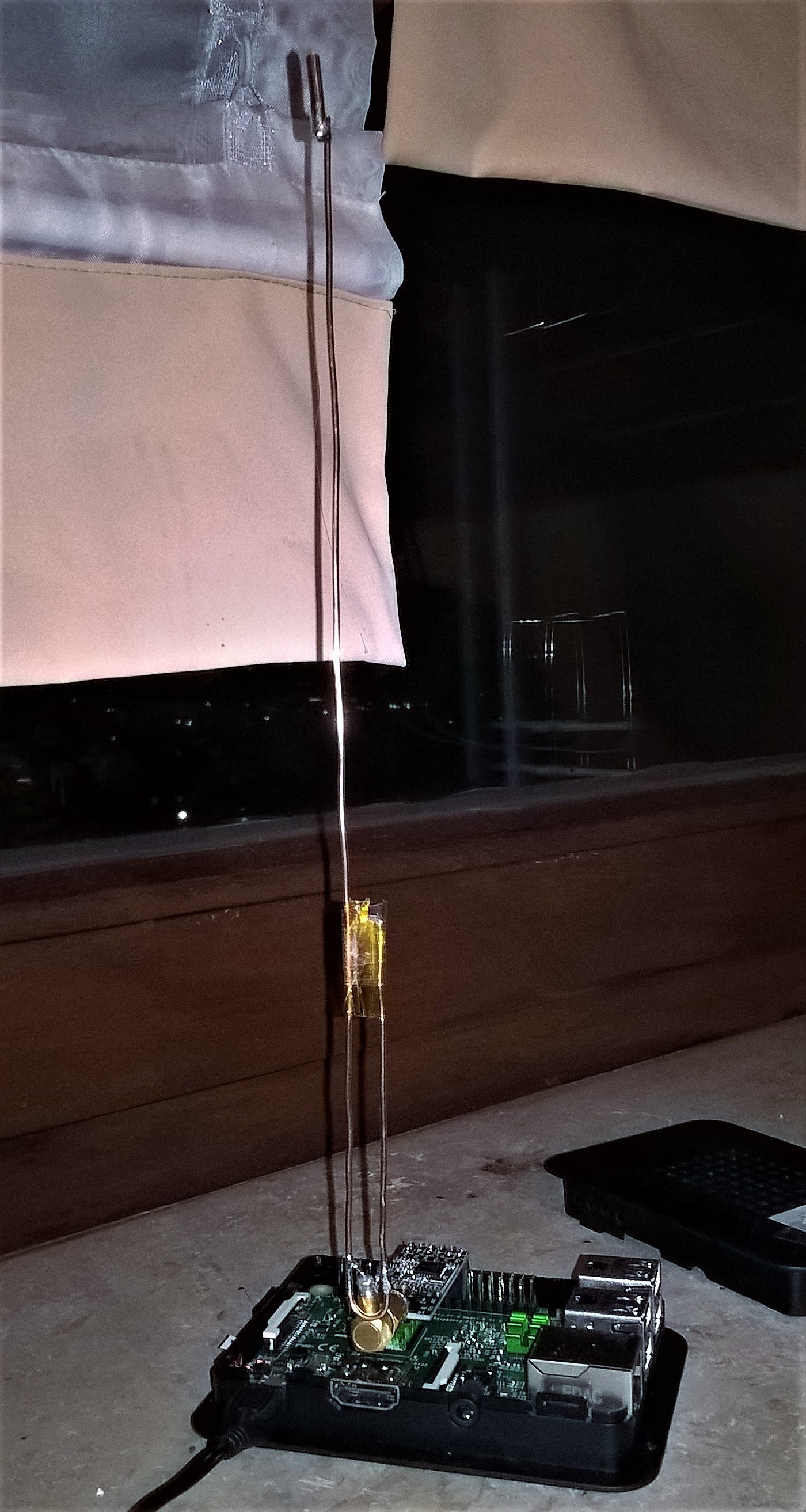
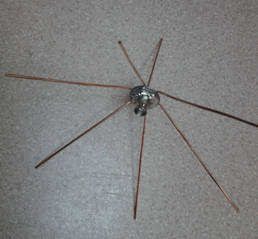
This is what I built:

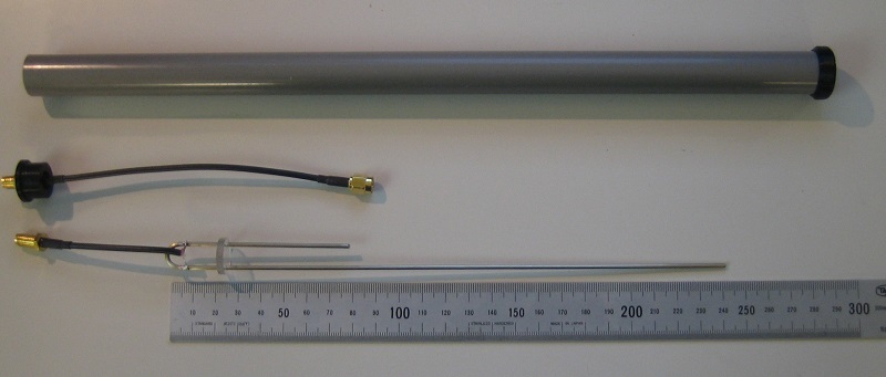
It’s a 2mm welding wire, bent around an 8mm drill bit to get the right curve. Three round polycarbonate discs keep it centered in a 16mm plastic tube and a standard SMA cable was cut and soldered to the antenna feed point.

The Antenna is 24.9mm long, the short part 8.3cm and the feed point is at 8mm from the bottom. This gives the following diagram on the network analyzer:

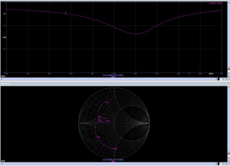
It is not that visible due to small numbers, but the dip is at 860 MHz and had a 13dB return loss. The bottom diagram shows the impedance: The horizontal center line is a pure reactive impedance so the antenna acts almost as a pure resistor (which is good).

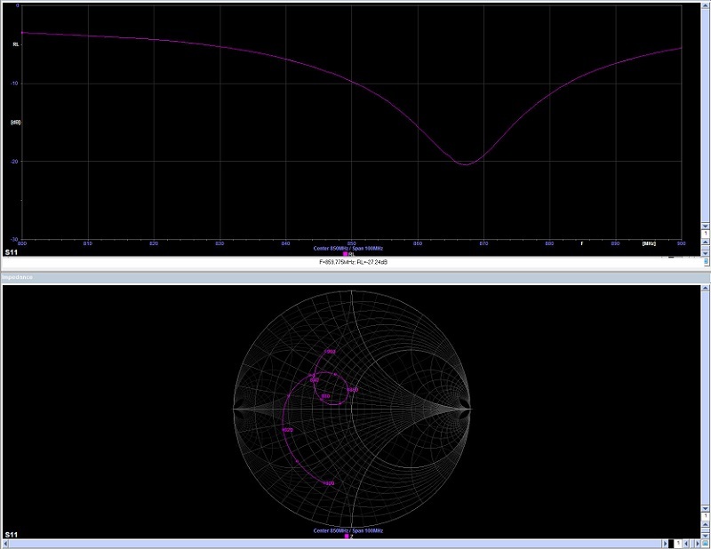
Moving the feed point to 9mm shifts the frequency at which the return loss is optimal towards 865 MHz but the impedance stays almost the same (only around a different center frequency)

These measurements were made with the plain antenna, not mounted in the PVC tube. Placing the antenna inside the tube results in a drop of the frequency of the antenna. This is due to the influence of the plastic around the antenna on the velocity factor. After recalculation I end up with a velocity factor of 0.93 resulting in 24.1 and 8.0 cm for the legs of the antenna.
I tuned the feed point (with the PVC pipe attached) and ended up with the feed point at 10mm. Moving the feed points a little bit does not change the behavior of the antenna that much. It stays somewhere between 15 and 21dB but 10mm seems optimal:

As a comparison I did some measurements on the “John Deer” antenna that’s being sold by a number of shops:

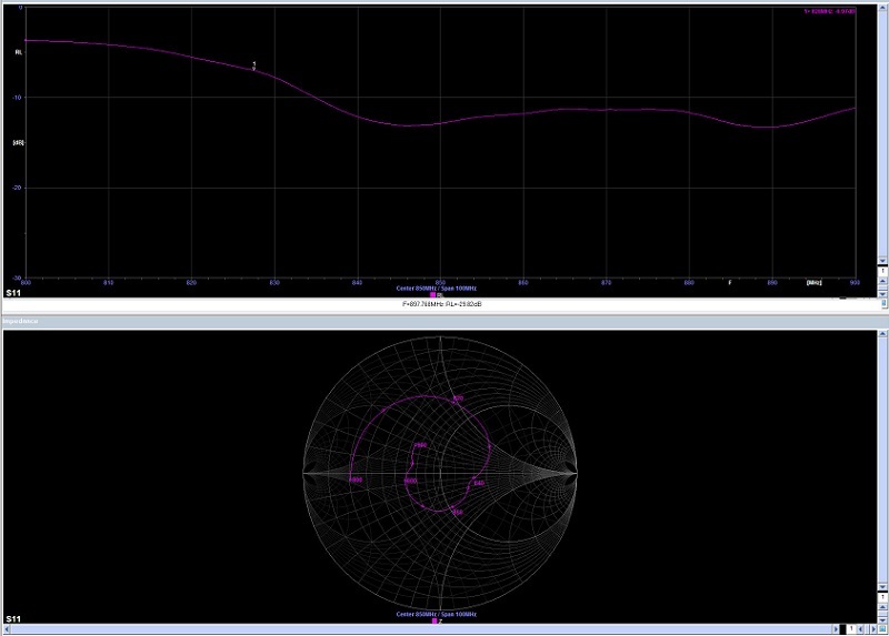
This is a dual band 868/915 antenna with 9dBi gain. The return loss is (at 13dB) a bit worse than with the J-pole but still not that bad. With a 5% power return loss instead of 1% is still good. With the small powers of a LoRa tranceiver it still won’t damage your equipment.

So I’m happy with the results. The antenna length is not that critical (+/- 1mm does not change the antenna that much) and placing the feed point at the right place is easy.

8 Likes

Nice story with good info Rob. Thanks for sharing.

Hi Rob,

Looks great, definitely one to try out :+1:. You posed a question:

How would you rate that? You used an analyzer that is able to produce quite fancy pictures, so probably it isn’t cheap? :blush:

Do you think we can get decent results with just the layout you described without using an analyzer?
I guess your PVC pipe passed the microwave test? (although 2450 Mhz is not 868 Mhz ;-)).

Expected gain is typically 2.2 DBi in the H(orizontal)-plane I understand? (assuming you put the antenna upright).

How about our 434 and 915 Mhz friends, I guess its just scaling the math?

How would you rate that? You used an analyzer that is able to produce quite fancy pictures, so probably it isn’t cheap?

Depends on what you call cheap.Compared to Rohde & Schwarz analyzers the Megiq VNA is cheap but for most of us around 4k EUR is a lot of money :wink:

I made way more measurements that the few posted. I played around with the feed point and the length of the legs of the antenna to see how much this influences the frequency and return loss. Looking at the fact that it was not that hard to tune the length and the position of the feed point within 1mm, I concluded that it is not that hard to create more antennas with equal performance.

I actually made the original antenna using the same calculator and number provided by Lex and that one was almost spot on. After placing the antenna in the PVC tube I calculated the new valocity factor and the new antenna was (again) spot on but could be improved by placing the feed point 1mm further.

I wrote something similar in my previous post but that got lost when WIndows 10 had the excellent idea of rebooting my PC before I could press the reply button :dizzy_face:

The next thing to do is to bend a few more welding rods and test then on the analyzer. The analyzer is something I can borrow from the office but it’s being used right now by another colleague to test a product we sell so I don’t expect any new results before end of next week.

Hi everyone,

On Saturday the 5th of November we are organising a LoRa hackfest at the SODAQ HQ to exchange ideas, thoughts, designs etc. on LoRa antenna’s and boards. You guys want to come?
We have some prizes for the best antenna design to be won!

Hello JanWillem,

I would have come, but that Saturday I’m all ready participate in the home brew exhibition at the “Dag Voor De Radioamateur” ( https://www.veron.nl/evenementen/dag-voor-de-radio-amateur-dvdra/ ) showing and demonstrating some of my home brew projects.

868 mhz flarm GP - http://www.bytebang.at/Blog/Building+a+cheap+FLARM+basestation+antenna#

FLARM wikipedia info
FLARM diy info

FLARM is an light aircraft early warning system on 868 Mhz ! :open_mouth:

2 Likes

Hi everyone,

I use such a J-pole antenna (left over from an older FLARM project) for my single channel gateway and did some range experiments with ttnmapper.

http://ttnmapper.org/experiments/map.php?name=DrTestRies_201703191619

Gateway: RasPi + RFM95 + J-Pole located indoors on my window board
Mobile station: homebrew 5/8 wavelength antenna with magnet-mount on my car + node with RFM95 module.

My antenna is made of 1.3mm solid copper wire:
251 mm (long leg)
83 mm (short leg)
7 mm spacing
feedpoint 9mm from bottom
no radome/pipe

2 Likes

26 KM ? … :yum:

Very nice, I guess this is also helping a bit :blush:?

Hi Batilan,

you solved of the riddle ;-).
As 868MHz is travelling almost line-of-sight, a slightly elevated gateway will cover most part of our flat 25km meteorite crater.
The J-Pole performed quite well. There are 20km points that are not elevated and some points were even logged out of small towns where no LOS is possible.

any chance of showing some pictures of your antenna build ?

No problem at all … but Rob65s design is much more what you like to see on photos.:sunglasses:

My motto is: “RF current has no eyes - so antennas do not have to be pretty” :wink:

The “big copperpart” has nothing to say, I just cut the wire too short while tuning and had to add something to get it longer. The capton tape is just for fixing the spacing between the wires and has nothing to do with the function.
Using a right-angeled SMA connector and 5mm cable, it is ready to use for indoor experiments without having to care about mounting.

3 Likes

Nice to find some fellow hams here :slight_smile:
At the time I found about LoRa I was fascinated by bringing together two hobbies of mine, ham and IoT. Having played extensively with JT65 in QRP and worked US and Brazil with only 5W and a 1m diameter magloop antenna I immediately jumped to the conclusion that LoRa and magloops can be best friends. Only to realize shortly after that this isn’t going to happen because there’s no way for a rougly 6kHz magloop bandwidth to accomodate a LoRaWAN’s 125kHz channel. The 2.5kHz JT65 bandwidth fits just fine although tuning the antenna is a bitch :laughing:
I’m currently looking to buy an outdoor antenna for my gateway but unfortunately the local market is pretty poor when it comes to 868MHz and most of them are unidrectional. I’d avoid purchasing one from abroad since I’m pretty worried that it may get damaged during transport. So I was wondering if I could use a 3/4λ antenna in 433MHz as a 1.5λ in 868MHz.
This is what I had in mind:
http://www.sirioantenne.it/en/products/uhf/cx-70-cm
More precisely CX 425 which is supposed to cover the 425-440MHz range. I know a thing or two about antennae, but I’d like to know if there are other things to be considered.

73s de YO9IYE

1 Like

Hi and welcome.
there also this antenna topic.

Thanks a lot for that tip, very interesting topic.

@BoRRoZ, @lex_ph2lb

Lex, did you build that cloverleaf antenna?
I am interested in circular polarization results as -unlike gateway antennas- nodes are often not positioned well for vertical polarization. Reinier (AI6CT, ex-PA3DJM)

Hi Reinier, haven’t been busy with antennas lately… think you must look at the rc drones market for inspiration

I didn’t made one for Lora but did some for the yearly ballon foxhunting which has a 23cm ATV transmitter in the payload.

photo5999345245906644078

photo5999345245906644079

I still have plans for building one and to put it i a antenna comparison setup.

More info on : http://www.antenna-theory.com/antennas/cloverleaf.php and https://oscarliang.com/make-diy-cloverleaf-antenna/

2 Likes