I’ve actually done some experiments for my low power battery-operated Arduino Pro Mini sensor board with RFM95W module following this guide i’ve reached 5uA of current draw from arduino in deep sleep.
Now, i need to design something that can allow me to acquire two type of signals: 4-20mA and 0/10V, i know that this can be done in a bunch of ways, but i need to use low-power designs in order to keep my sensor run on battery for at least 2 year.
I’m planning to use standard AA batteries like these old-fashioned Duracell Plus Power, they are claims to be able to deliver 3.016Ah per single cell and i want to use two of them in series, so i can reach 3V.
My maximum target consumption during sleep can be around 20-25uA.
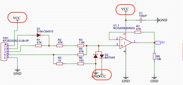
My thoughts drive me to this schematic: using a low power NCS20062DR2G in this configuration i can read 4-20mA, 0-10V…and in addition a dry contact from external sensors/systems.
In order to put everything on battery and keep it “zero” on consumption during sleep, i’m thinking to attach the VCC pins to a Arduino digital pin output and then do a digital write high (putting it to 3V).
Anyway, i have some doubts about this design:
How it works when the battery discharges…say at 2.3V?
It can be a good solution for this specific purpose?
I’m completely opened to alternative solutions, please note that this is only my initial idea.
Standard AA batteries have a very bad discharge profile for use in IoT solutions. You would either have to add a push/pull converter to keep the voltage at a reasonable level as long as possible (check the circuit of the Generic Node for a possible example) or make sure everything works with a marginal voltage.
Another solution would be to go for batteries with better characteristics. Saft (and probably other vendors) have a battery selector for this purpose.
The opamp is powered from the main voltage input through a current limiter which would allow it to process higher voltages - it is not powered by 5V (VCC).
Additional:
I’d not route VCC out through a connector just because - anything could happen to blow the output of the Arduino - if your device is powered externally, don’t risk the Arduino - and anyway, the schematic says V+, not 5V (VCC). And the connector has that many pins because that’s what the Iono uses - you only need two, possibly three because …
The input circuit allows for digital and 0-10V inputs too - so copy n pasta means you’ve got an over complicated circuit when you only need one input source.
My design calls for a nominal 12v power supply so would not really be suitable, however IF the OP has an externally powered 4-20mA device then he could very likely power the LoRa transmitter from that via a small super-cap and zener diode no need to scrimp and save power if you have 4-20mA available, all you need worry about is covering the occasional and brief ~100mA transmit pulses.
If you read carefully what i’ve asked to @fishbeetle (the proposed idea to use a supercap to get power from 4-20mA loop and power the node), you’ll find how much useless is your disappointment.
As you didn’t refer to my time taken analysing your circuit, warning you it wouldn’t work as expected and the present I gift-wrapped for you, I thought you, like others here, had skipped the present unwrapping.
I’ll divert my disappointment in to your lack of gratitude.
Regarding my reading abilities, maybe there are some neurological factors you should take in to account - not everyone is a whiz at reading.
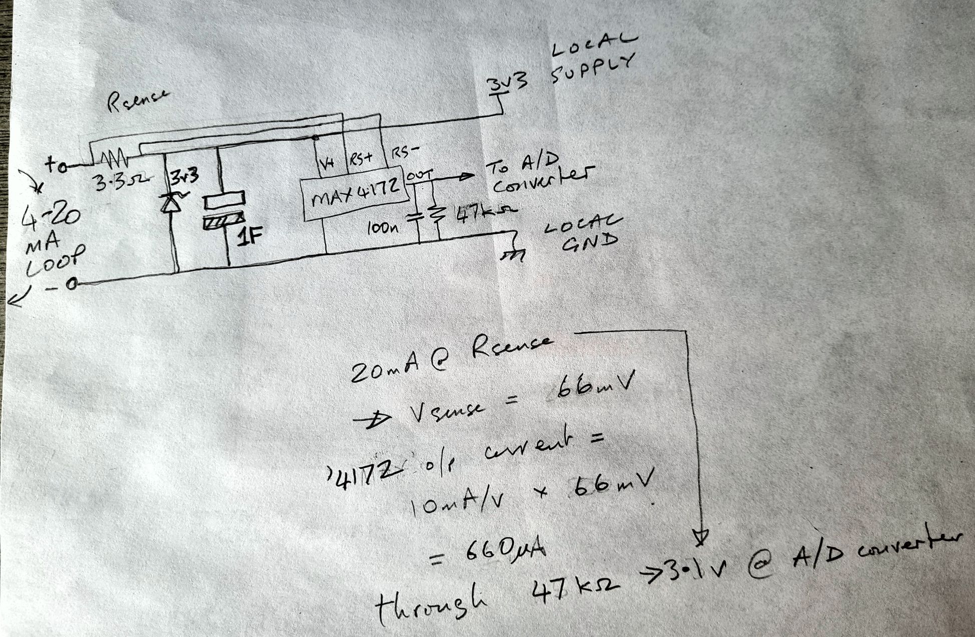
As for the schematic, it’s a capacitor & a zener diode although I’d be inclined towards using an LDO instead of the zener.
The attached jpeg shows a first stab at the problem, should give you some ideas. Afraid I can’t enter into any further discussions on the subject. But you can hire me if you like!
Hope this helps.