The gateway should show all LoRa traffic, even if it is not using LoRaWAN. Even TTN Console will show gateway traffic it cannot decipher.
(In LoRaWAN terminology there is no such thing as a gateway node.)
The gateway should show all LoRa traffic, even if it is not using LoRaWAN. Even TTN Console will show gateway traffic it cannot decipher.
(In LoRaWAN terminology there is no such thing as a gateway node.)
I’ve just updated the TTGO v2 Case for ESP32 LoRa boards. Use last 3 STL files (v2 at end)
Improvements:
ordered one of the new version 2 via Treatstock. 
I followed directions in post 123 from part 1 of this thread. I’m using the Heltec modules.
I loaded the single channel gateway and it TTN says it is connected, last seen refreshes every few minutes. But no data posts to TTN.
The only part not clear is the end of your post that says ‘select your frequency’. I think i’m supposed to use the 915mHz range for USA.
loraModem.h says if in doubt choose the first frequency in the array and comment the others. But they are all 868 range.
What frequency should I use for the single channel?
And where do I set that single channel in the example Send node from the same post 123?
I’m not sure how to debug this as the serial monitor on the ESP-sc-gway node seems to be working and waiting.
Gateway ID: xxxxxxxxxx, Listening at SF7 on 914.900 Mhz.
setupTime:: Time not set (yet)
Time: Tuesday 20:58:54
Gateway configuration saved
WWW Server started on port 80
And the send node says
“Packet queued
122183690: EV_TXCOMPLETE (includes waiting for RX windows)”
Does the send node example default to a different frequency and where would i change that? I need help please.
Does anyone know of a definative list of which pins on an ESP32 you can use for project I\O and which ones you need to avoid ?
I have been checking on a NodeMcu32s, and some of the pins, if used as General purpose I\O pins can stop program uploads, they are used for the internal flash for instance.
I hope this one works better than the previous one.
Thanks @arjanvanb.
I set the send node and gw node back to the default code with 868.1 frequency, and now i am getting data readings on TTN.
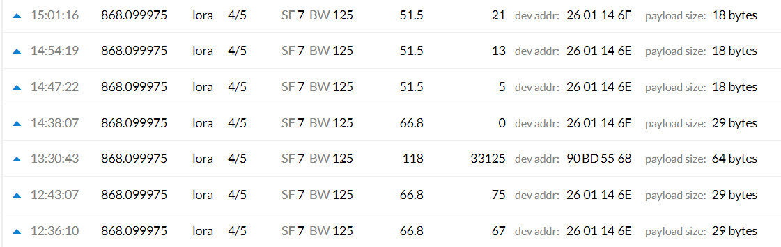
The msg at 13:30:43 is from an unknown node, so my gateway does pick up others on the 868 frequency. The data messages before that are with no send node plugged in, and the payload is 29 bytes. Once i plug in the send node, the packets are 18 bytes.
Does this example SC GW send a default 29 byte message in it gets no payload from a client node?
It looks like the physical payload field starts with my device address. Is there a standard encryption / decryption function that this example gateway uses so I can learn how to extract the actual data?
It does send status messages, but not message like you see in TTN Console†. Gateways don’t even know what nodes exist; gateways just listen to the LoRa radio signals and forward those to the backend servers. So, the 29 bytes are really received from some node. And if the DevAddr looks familiar then it’s probably your own node. (If not, then it might not even be LoRaWAN at all, even though TTN Console assumes it is, and shows a DevAddr. It certainly is not just created by your gateway.)
That’s not the subject of this very topic. But the DevAddr is in the 2nd to 5th bytes. See the specifications and https://runkit.io/avbentem/lorawan-packet-decoder/branches/master
(Again: there is no such thing as a “gateway node”. With “nodes” LoRaWAN refers to end-devices, not to gateways.)
† Unless you use some special gateway that mimics a node too, but then you need to be far more specific about which gateway software you’re using
Great news ! Heltec released the schematics for their boards : https://github.com/Heltec-Aaron-Lee/WiFi_Kit_series/tree/master/SchematicDiagram
Now we will have an easier job trying to find how to reduce their power consumption.
That’s interesting news, thanks for sharing here.
I took a first look into.
Don’t see big chances for lowering power consumption. Because the peripherals are “dumb”: charging circuit and UART/USB converter cannot be controlled by main CPU.
Unfortunately the probably most interesting part for RF performance tuning is missing: The schematic does not include the RF path. Maybe because it’s considered as secret sauce - or simply bad designed?
It is there, at the bottom of the wifi_lora ones, but without filtering passives values.
The other boards (Wifi_kit) don’t have the lora feature.
@gebir did you had a chance to get the .stl files?
Thanks for making this more clear.
I understand the node and gateway differences.
I loaded the single channel gateway https://github.com/kersing/ESP-1ch-Gateway-v5.0 and registered with TTN and is says connected.
For the send node I loaded https://github.com/matthijskooijman/arduino-lmic and the sketch that @Curlywurly listed in part 1 of this thread, post 123.
As my previous post shows a snippet of TTN messages, when i have the gateway running and the send node unplugged, my TTN console gets messages of 29 bytes from device address of the device that is unplugged and not sending. When I plug in the send node the TTN console gets the correct message of 18 bytes from the send node.
My presumption is that the gateway is sending a message at the last known schedule with the last know device address.
I’m trying to understand this. I thought this TTN protocol was to send the least amount of data with the minimum amount of traffic to keep the network clear. i will try to read and understand the 1ch-gateway code better. If my only send node is UNPLUGGED, it cannot be triggering the gateway to send.
I sent ask to seller, now waiting.
Hi there,
I took some time to successfully tested and joined TTGOV1 and Heltec Lora32 to speak to TTN.
Seems to have around sketch running on these device using OLED and sort of driven menu on the screen (like the one shown on V1 3D printing) but I’m unable to find anyone.
Could be cool if someone wrote one to test Lora with sort of UI with button/OLED menu?
Any example to inspire from?
What kind of menu do you mean?
What would you expect to do it?
Just curious, wanted to see how it’s handled. A menu selecting SF, ACK, Len, … and send test packets for example ![]()
Ah ok, so you are looking for a test node with some ‘dashboard’ where you can tweak several options and settings for (connection) testing purposes. 
That is also on my ‘would like to have/do’ list. 
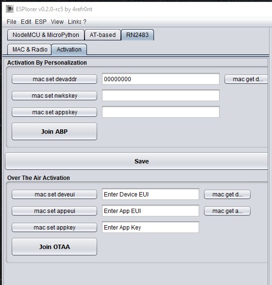
Also neat would be the possibility to easily (‘on the fly’ + node restart) switch between OTAA and ABP activation. But not practically feasible because the node type has to be defined on the backend. This can possibly be done via an API call but would be too much hassle and too complex.
A workaround is to create two separate (logical) devices in the TTN console for the same physical node. One for OTAA and one for ABP. This will allow the node to be switched from OTAA to ABP and vice versa for testing purposes without requiring changes in the (hardcoded) configuration on the node or backend.
Another nice option would be to have the UI run on a phone, connected via BLE with the node. Useful for field testing and does not require display, buttons, rotary encoder etc. on the (test)node. ESP32 already has the BT built in.
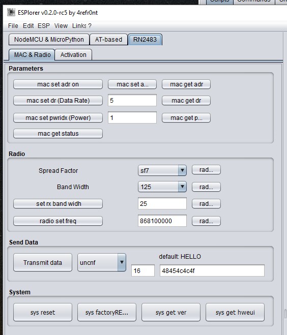
passthrough sketch and this freeware… (works only with rn2483)
Nice, but that’s a complete IDE targeted at ESP8266. Not a solution that runs on the node independently that can be used for easy mobile field testing.