Another option to work around the issue (not a fix) may be to throttle the current usage during power-up, i.e. gradually start initializing/using Wifi and Bluetooth interfaces with some pauses in between from startup.
This may help prevent the voltage sink during start-up from battery that causes the brown-out.
The question here is probably: How is the power circuit on the TTGOv2 board designed?
I assume that the 3,7V battery drives some kind of step-up/step-down circuit, and maybe this circuit lacks of peak power.
350mA spikes @5V is 1,75W peak. This shouldn’t be a problem for a LiPo cell?
Unlikely to work, but try putting a 100uF cap across the 3.3V / ground.
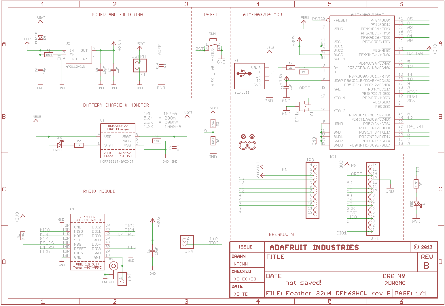
Chances are, the power circuit is similar to a feather board as per here
In this board there are 2 separate chips (circuits) involved with power.
MCP738312 - Battery charge circuit (5v Vbus to battery Vbat)
AP2112 - Power supply Circuit - Linear Regulator - 2 inputs of battery Vbat and 5v Vbus, with a regulated output of 3.3v
N.B. Make sure you check the lipo battery voltage and 3.3v supply when not connected to USB - you may have a bad battery?
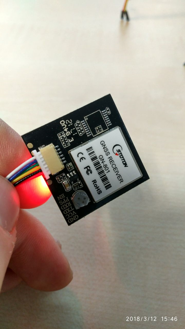
I am playing with the TTGO V1 OLED and I am trying to make GPS work. I ordered an GN-801 from Aliexpress.
I could not find good examples for this particular GPS module because this one has 6 pins ; GND, VCC, TX,RX, PPA and EN.
I connected everything but PPA and EN. I am not sure what to do with these. Here is what I have :
on top: #define GPS_RX 23 #define GPS_TX 17
HardwareSerial GPSSerial(2);
SETUP:
GPSSerial.begin(9600, SERIAL_8N1, GPS_RX, GPS_TX);
LOOP:
while (GPSSerial.available() > 0)
{
Serial.print(GPSSerial.read());
}
Issue fond.
esp_deep_sleep_start() - causes spikes in some GPIO - e.g SPI SCK pin, at the same time GPIO14(LoRa RST ) seems to be hi-Z -> spike occures in this pin. The result is reset SX1276.
Temrorary I added pull up 2KOhm and SW reinitialize of SCK as input.
maybe graceful stop of spi before esp_deep_sleep_start() coud be the final solution. Needs to be tested . Sorry No time for it.
Just another disappointing result from these boards.
I have tryed two Heltec. In term of coner range they behaves similar.
Test setup – Transmitter Raspberry pi at home with decent Sx1276 module. –W=125KHz SF=11
Node 1 – Heltec board #2
– at home two floor difference - packet RSSI -95dbm
100 meter -110…115dbm after 300m problems
Best achived distance – 500…700meters. min achived RSSI -123dbm
Node 2 – Heltec board #2 – similar to Node 1
Node 3 – the same good quality module as transmitter at home Arduino atmega2560 SPI
a. At home RSSI -48…-49dbm
b. 1km – RSSI -100dbm
c. 2km at wet wood area - -120…-122dbm
d. 11.15km – in open agriculture are
Transmiter was staying the same an test was done at the same time interval. Antenas ware the same groundplane – swapped between nodes.
Used the same GPS module, didn’t connect the PPA and EN at all. It worked.
I’ve used pins 35 and 34 for RX/TX on the TTGO V2.0
The TX of GPS connected to 34
The RX of GPS connected to 35 (I’m not using it currently but you could use it to configure the module over internal messages)
Take care the colors on cables are wrong. Use the text writen on PCB.
Red is GND
Black is VCC and so on
Interesting stuff - thanks for sharing - might be good if you posted this on a separate thread?
The combination of an ESP32 and Lorawan is extremely beguiling and ideal for something like this (power requirements are perhaps the only problem) .
Where do you see your “PAX counter” leading?
Also, thought these would give food for thought
I added legal note in the readme of the repository.
The code stores scanned MAC adresses in RAM only, and keeps it temporary for a configurable scan time (default 240 seconds), then deletes the RAM and starts over. So no kind of tracking or persistent storing of personal data and no other kind of analytics than counting of MACs is implemented.
I am new to arduino, TTN, radios… everything.
I searched this because of a Christmas gift, I think now I am addicted. I need rehab center soon.
I am reading everything from multiple forums, I have listened at least twice to Herr Spiess’s youtube videos related to LoRa and ESP.
I ordered 3 of the Heltec boards and Wemos D1 Mini and Mini Pro and the Hallard cards and RF95 radios. all 915 US. Western Colorado.
Yesterday i dived in and started with the Heltec boards. As has been noted, not much QC. 2 Heltec boards light up and init and display. 1 has cracked OLED when opened. I used the examples listed and got 1 sketch loaded to be LoRa receiver and the board with cracked OLED talks fine. Both send and receive work correctly and can watch via serial monitor in arduino IDE. One board with working OLED says it is fine in serial monitor, but nothing ever gets to receiver node.
i changed receiver node to example from @CurlyWurly, registered it with TTN, and it says it worked. WOW. Changed the sending board to send sketch from @CurlyWurly and serial monitor says "Packet queued
122183690: EV_TXCOMPLETE (includes waiting for RX windows)
", same as other past posts. Serial monitor on single channel GW does not show anything received, nor does OLED on GW. Just says READY and GW serial monitor says connected to wifi and i can connect via browser to GW.
All that to say I’m stumped. I think I have the DEVaddr and keys correct, but do they even need to be correct to get from the send node to the GW node?
I switched this morning to learn about the wemos D1 mini and with a simple water sensor i am getting about 400meters max from my house with stable readings, after that NOTHING. So, i really want to figure out the LoRa radios. I need to transmit 3-5km in mostly open farmland region.
…my wife does not think i should buy spectrum analyzer and oscilloscope. But she says it is OK if I buy Andreas a beer IF i take her to Switzerland also.