This “Arduino IDE board extension” is for multiple TTGO boards, including some with ESP8266, hence the name.
But you are right this repository is not very interesting , documentation not updated to fit the specifics of the boards, etc.
This “Arduino IDE board extension” is for multiple TTGO boards, including some with ESP8266, hence the name.
But you are right this repository is not very interesting , documentation not updated to fit the specifics of the boards, etc.
I got the case from the 3D print service (treatstock) these days.
The TTGOv2 board snaps exactly into it, but the antenna with the pigtail SMA jack doesn’t.
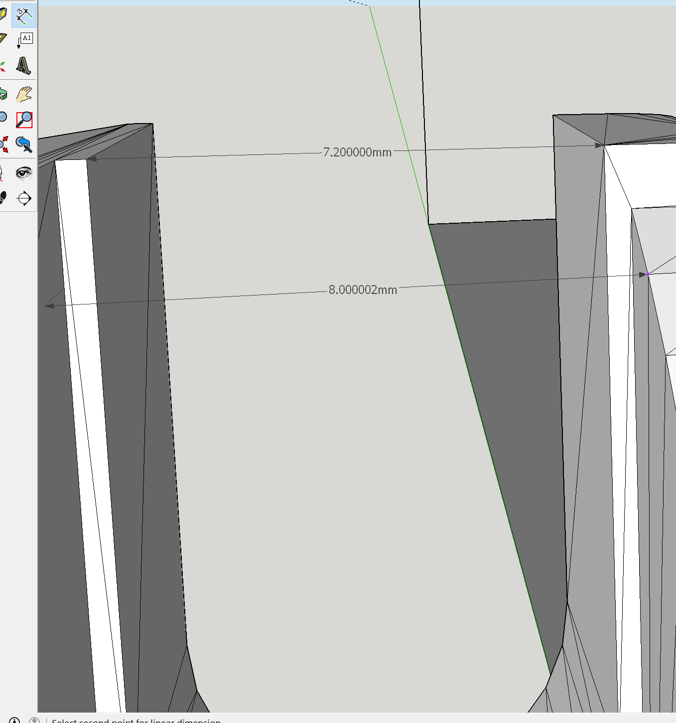
The hole for the SMA jack is to narrow, causing my case break at the left side when trying to fit the SMA jack into it. 
Mounted.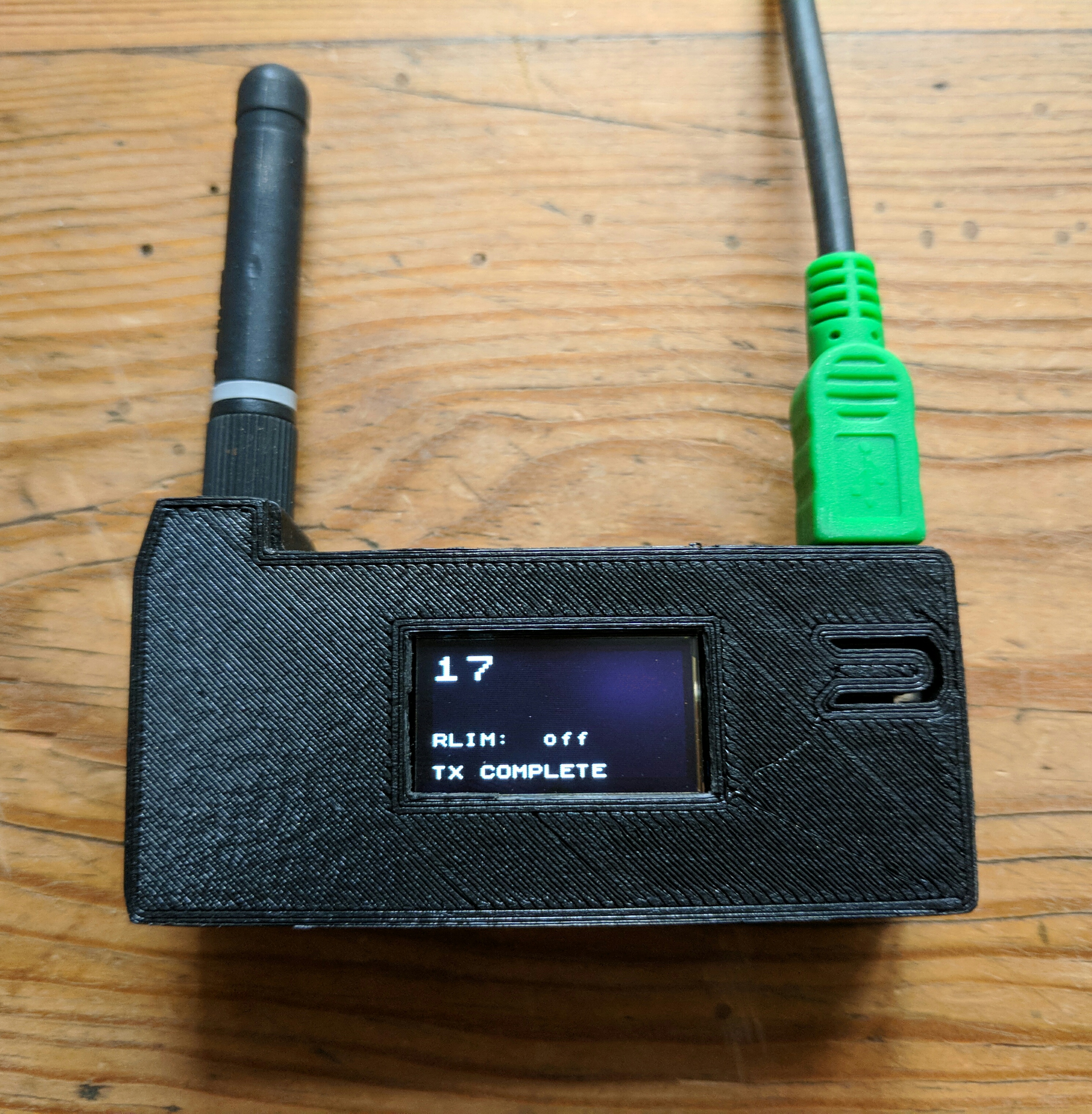
Mine fitted well. Did you printed on 0.2mm resolution?
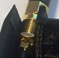
Can you make a photo of the area to see what’s the problem?
With 3d prints you need always to consider filing a little the surfaces before assembling.
Also, if the objects break you can use soldering station for fixing objects.
i don’t know what settings were used for printing, because i ordered your file from treatstock, a 3d printing service.
But since the TTGOv2 board and the screws matched exaktly, i think the case was printed with correct dimensions.
The hole for the SMA jack is not wide enough to take the nut from the SMA jack.
If it is not intended that the nut sits inside the hole, your SMA jack seems to be longer than my one.
I’ve tried two antennas. The original one and another one purchased from ebay.
Both fitted well with my printer.
Are you sure that you screwed in the antenna connector fully on the SMA jack?
My one was to short for fitting in the case opening with mounted antenna.
Andreas Spies newest excellent video abou antenna basics, as of today:
I have a strange effect with my TTGOv2 board:
If i run it on USB power, my application code works as expected.
With the same code, when i run the board from battery, it crashes at a certain point.
Debugging is difficult, since using a USB cable surpresses the failure.
The crash is not erratic, it seems it happenes always at the same point in the code, but i can’t figure out where exactly this happenes.
Has anyone an idea, how battery operation could affect code execution behaviour in TTGOv2?
Does your TTGO board have TXD from USB\Download connection on one of its pins ?
When connecting the USB except for it’s +5V line and power the TTGO separately via battery, you can use the serial port without having to power the TTGO via the serial port.
This will require of course some custom cabling.
Another option is to output diagnostic messages to the OLED display instead of to the serial port.
Meanwhile i checked the battery is full. And yes, it was fully loaded from TTGOv2 socket. If i start the board and app code with USB power cable connected it runs, even if i unplug the USB power cable after startup it continues running on battery.
But when it is started from battery, it crashes at a certain point in the app. Strange!
TTGOv2 is reported to feature a USB/UART CP2104 chip, instead of a CP2102, as found on TTGOv1 and heltec boards. Maybe this has influence on this effect?
I think that should not make any difference.
https://www.silabs.com/community/interface/knowledge-base.entry.html/2016/01/13/differences_between-nLJ7
My TTGO v2 runs just fine when I start it from a LiPo battery.
Meanwhile i checked this with a tweaked USB cable. It turns out the board throws a “brownout detector was triggered”.
That’s still strange, because when i start it from USB power, then detach USB power, it keeps running on battery for 2 hours.
rst:0xc (SW_CPU_RESET),boot:0x13 (SPI_FAST_FLASH_BOOT)
configsip: 188777542, SPIWP:0xee
clk_drv:0x00,q_drv:0x00,d_drv:0x00,cs0_drv:0x00,hd_drv:0x00,wp_drv:0x00
mode:DIO, clock div:2
load:0x3fff0018,len:4
load:0x3fff001c,len:812
load:0x40078000,len:0
load:0x40078000,len:11404
entry 0x40078a28Brownout detector was triggered
Have you tried to use another battery?
Have you checked if the battery wiring (including connector) is ok?
The issue can be board related but may also be related to a battery issue, or poor battery wire/contact/connector.
This appears like an issue where the voltage drops when switching it on, not ably to sufficiently handle the switch-on current peak.
This seems to be a common problem with power design on ESP32 boards, meanwhile i found several reports on this issue in the ESP32 forum.
My code runs on Heltec and LoPy and LoPy4 boards without any battery problems, but not on TTGOv2.
I discovered that the OLED display on TTGOv2 does not behave like the display on Heltec: it remains on while flashing. Maybe it’s powered by 3,3V not 5V and this makes the power situation on the board fragile, but this is pure speculative so far.
Meanwhile i tried it with a second TTGOv boars, and another (bigger) LiPo battery.
Same problem. It seems TTGOv2 has a hardware related problem when enabling Wifi, BLE and LoRa on battery
Display staying on when flashing is quite common. It probably has to do with lack of (or not using) reset. This is normal behavior with the SSD1306 OLED displays that do not have a reset pin (with the U8g2 library at least).
If you don’t clear the display it will show its contents as long as the display stays powered.
I power all my OLED displays from 3.3V, no problems with that.
Why complicate things and power OLED display from 5V on a 3.3V device. That would be very impractical and/or inefficient.
Add code to toggle spare GPIO pins high at certain points in your code. e.g. pin 1 at start, pin 2 after serial defined. etc
Put a cheap logic analyser on these pins, press record and start up the ESP32.
It should help to narrow down things?
N.B. this is interesting to know
"the green BAT trace is the current consumed from a 5v battery…(The ESP32) wakes at 60-70mA, rising to around 140mA once wifi is turned on, with short spikes to over 350mA.
Total usage is 204mAs…
_ the esp8266 uses around 50mAs (maybe less, I forget the latest results)…"_
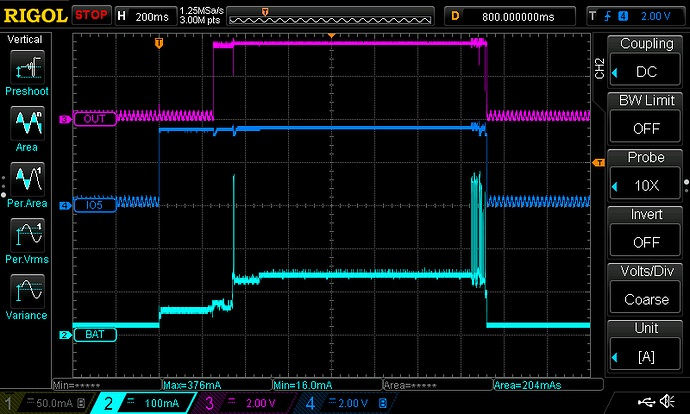
https://forum.makehackvoid.com/t/playing-with-the-esp-32/1144/6
Another option is to use a spare USB cable and cut the power line. That way you get serial messages while the circuit is powered by battery
An ‘enabled’ LoRa device uses very little current, only 2mA in standby mode.
So if the addtional current consumption of LoRa receive or transmit were the cause of the problem, you would be able to identify that by monitoring the serial console output on the TXD pin.