…but has no LoRa chip on board? 
The big ESP32 book. The official pay-as-u-like link:
1 Like
TTGOV2 joins with LMIC TTN-OTA example sketch but does not continue to transmit next messages.
I used: // Pin mapping
const lmic_pinmap lmic_pins = {
.nss = 18,
.rxtx = LMIC_UNUSED_PIN,
.rst = 14,
.dio = {26, 11, LMIC_UNUSED_PIN},
};
and
SPI.begin(5, 19, 27, 18);
and get in Serial:
rst:0x10 (RTCWDT_RTC_RESET),boot:0x13 (SPI_FAST_FLASH_BOOT)
configsip: 188777542, SPIWP:0xee
clk_drv:0x00,q_drv:0x00,d_drv:0x00,cs0_drv:0x00,hd_drv:0x00,wp_drv:0x00
mode:DIO, clock div:1
load:0x3fff0018,len:4
load:0x3fff001c,len:956
load:0x40078000,len:0
load:0x40078000,len:13076
entry 0x40078a58
Starting
Packet queued
4450: EV_JOINING
432642: EV_JOINED
and I get two messages, one for activation and one with payload. Framecounter disabled.
Where is the mistake?
Hello
I have investigate how to debug ESP32 Heltec wifi LoRa board using JTAG adapter and looked at this forum without success
In Kolban’s book on ESP32, Jtag adapter must be connected to GPIO12, GPIO13, GPIO 14 and GPIO15 ESP32 pins.
But Heltec wifi LoRa board, GPIO14 is used for LoRa_RST and GPIO15 is used for OLED_SCL. In Heltec pinout diagram we can see these two pins must not be used for other purpose unless you know what you are doing.
Does it mean we cannot JTAG debug Heltec board or is there a workaround by assigning other pins to JTAG signals ?
Thanks in advance if you have an answer
Hi,
I saw you experiment with the TTGO V2 board. Does yours work with the LMIC library?
Yes, it does.
Don’t forget to wire DIO1 on the board, as explained in the top of this topic. Otherwise LMiC won’t work.
Which pin is DIO1 on the LoRa module? Because I think, mine are somehow wired already.
Read top of this topic.
If you have TTGOv1 you don’t need to wire but must check board RF quality.
If you have TTGOv2 you certainly have to wire for LMiC.
Depends on the LoRa module, and you would expect the data sheet for the module to say which is the DIO1 pin ?
Hi,
I’m trying to design a very small breakout to be able to measure battery voltage on Heltec, TTGO, I don’t see any pinout with VBat, can any V2 here is able to tell me if we can grab vbat somewhere ?
looks like something like that
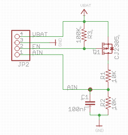
thanks
Now I got it. I was fooled by the diagram where it said that DIO1 of the LoRa chip was connected to GPIO11. And the ohm meter showed the same… But The pin named GPIO11 is not connected to the ESP (would be anyway useless as I discovered later).
Now I connected the pin labeled GPIO11 to GPIO13 and changed the pin mapping to
// Pin mapping
const lmic_pinmap lmic_pins = {
.nss = 18,
.rxtx = LMIC_UNUSED_PIN,
.rst = 14,
.dio = {26, 13, LMIC_UNUSED_PIN},
};
Now it works.
Thank you very much for your help.
In post #260 you find schematic for TTGOv2.
Schematic says, no VBat anywhere, but it must be present at least on battery connector 
Sure and maybe easier to solder on ON/OFF battery switch ![]()
Look what I received this morning,
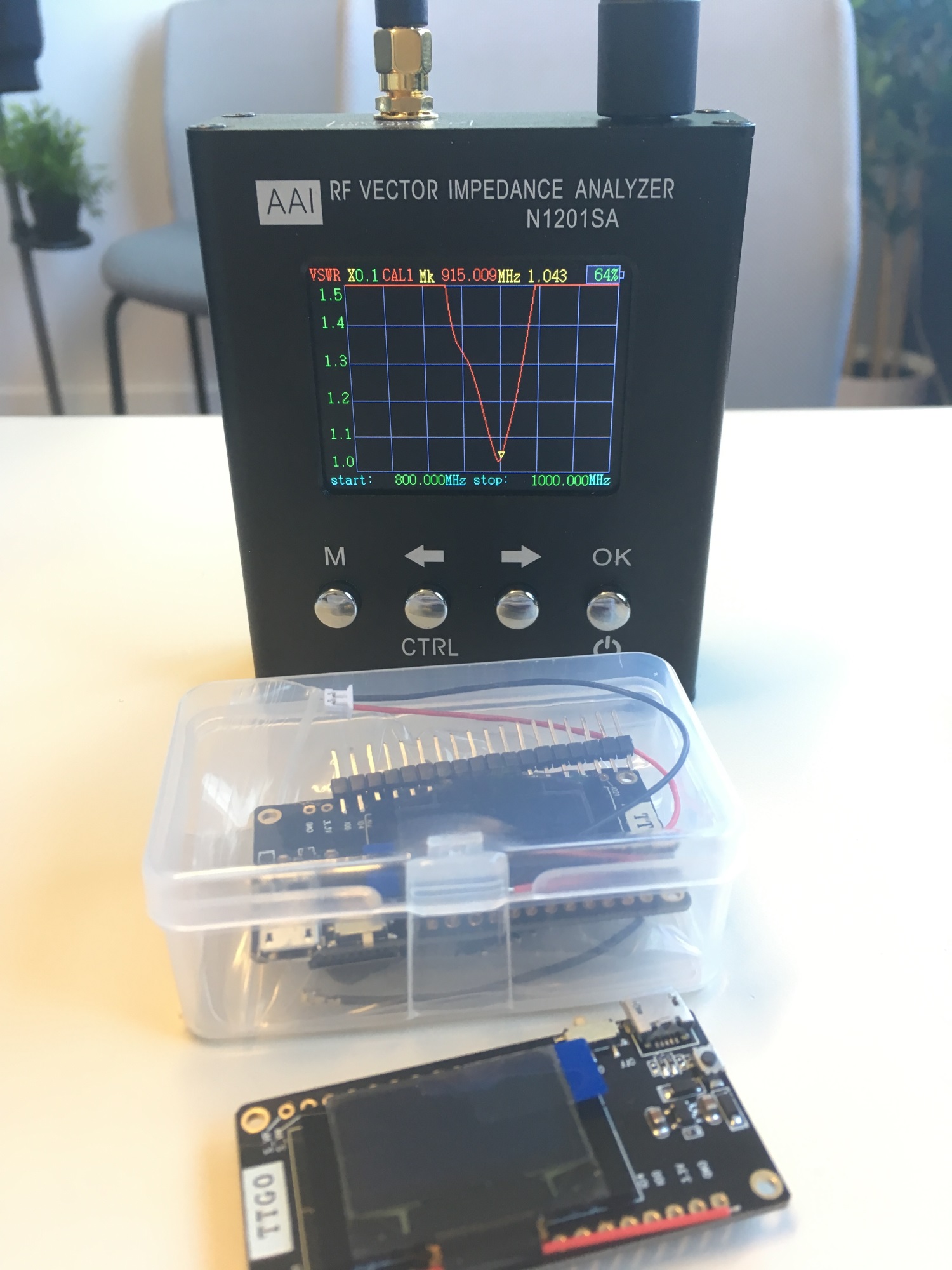
Time to test new amazing tool, and looks like design was for 915Mhz not 868Mhz, al least for Antenna. I noticed the same for Heltec and TTGO V1 antennas.
So have anyone tested range of these devices (on EU 868 of course) on real field to compare to real 868MHz devices
4 Likes
I changed the Heltec/TTGO antennas with a quality type made by “LINK”, gives some improvement.
But the Heltec/TTGO antennas are not all identical, there are at least to different types, looking the same from outside. See my post above.
Also waiting for VNA, but ordered the 2201 version, for measuring inline between antenna and board. But still on “Ali express shipping” and will need another 3-4 weeks i guess
1 Like
Thanks,
The OLED on V2 is not displaying correctly, all is displayed on the 1st lines only, did I missed something? Maybe oled type is different?
Sure did you took AliExpress Express Shipping, usually takes less than 2 weeks
OLED on TTGOv2 should work out of the box at least with the paxcounter software. Didn’t try anything else yet with it.
Maybe they changed OLED type, but i won’t expect this, since all seen boards had SSD1306 controller yet.
Caveat: The glas of display is very crisp. I broke one when the board was fallen from desk to floor. That caused a display hardware error, now only every second pixel dot line is alive, rest is dead.
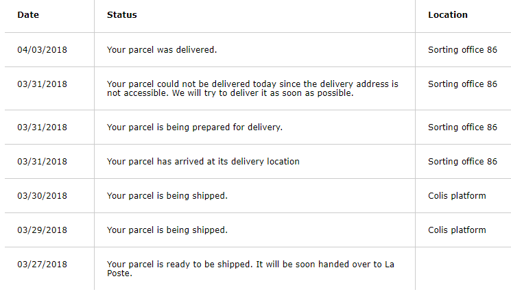
Yes, is express, with shipper named “Courier”. Parcel was sent from Shenzen on 28.3. and arrived in Amsterdam Airport on 31.3., “custrom clearance processing”. So it made it’s way around the globe pretty fast, but since it is stuck in Amsterdam nothing heard from it.
Here is my boot screen
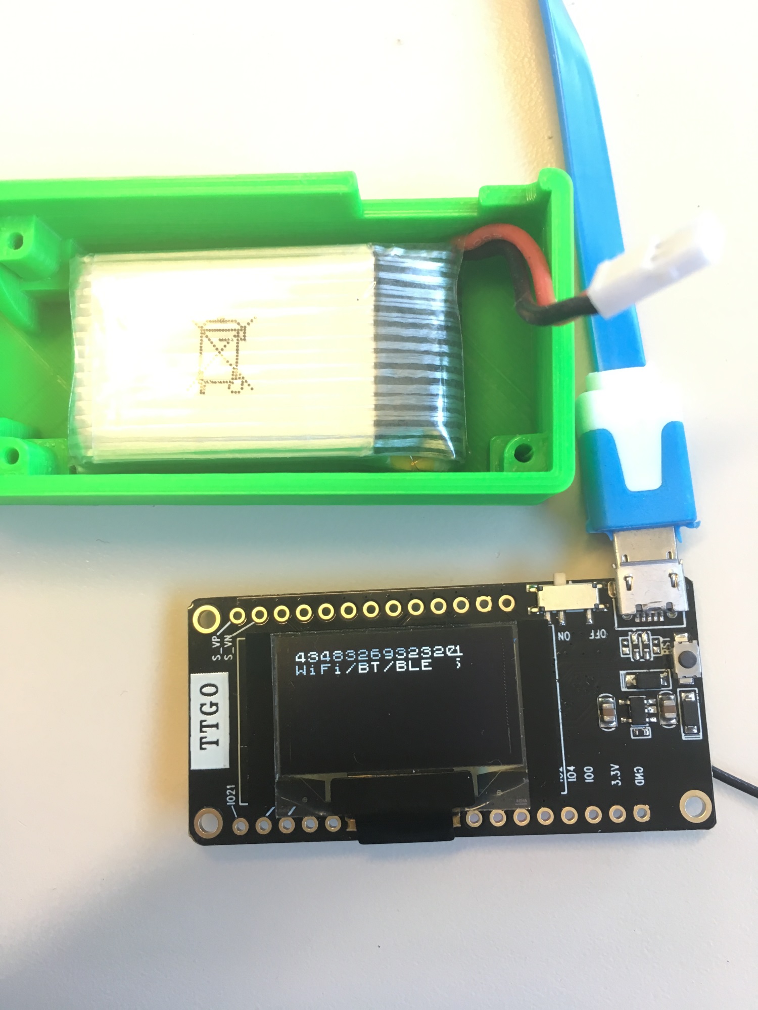
BTW what battery you put into enclosure, since charger is set to 500mA I’m unable to find any 1000mA battery fitting in the enclosure ;-(
ordered N1201SA on ebay march 27th, received on April 3rd, not bad and it took 4 days to make the last 1 kilometer amazing !!!