… sorry for the confusion. This is a bug in esptool.py. The chips are revision 1 silicon, but only recently have had the efuse bits set to confirm the CPU frequency rating (previously these efuses were not set).
As WiFive says your chip is revision 1 silicon, 240MHz rated. Will fix the bug in esptool.py ASAP.
/* EFUSE_RD_CHIP_CPU_FREQ_RATED : R/W ;bitpos:[13] ;default: 1'b0 ; */
/*description: If set, the ESP32's maximum CPU frequency has been rated*/
#define EFUSE_RD_CHIP_CPU_FREQ_RATED  (BIT(13))
#define EFUSE_RD_CHIP_CPU_FREQ_RATED_M  ((EFUSE_RD_CHIP_CPU_FREQ_RATED_V)<<(EFUSE_RD_CHIP_CPU_FREQ_RATED_S))
#define EFUSE_RD_CHIP_CPU_FREQ_RATED_V  0x1
#define EFUSE_RD_CHIP_CPU_FREQ_RATED_S  13
The internal temperature sensor unfortunately has a pretty big random offset that differs from chip to chip. It can be useful to keep track of temperature deltas, but you can’t really infer an absolute temperature from the value. We may have some more accurate ways to get the temperature, but at this moment they’re not implemented in esp-idf yet.
I have checked that temperature differs a lot from chip-to-chip (20 degrees celsius).
I have also checked that when WiFi is turned on the temperature increases but measuring with a termometer the behaviour seems to be quite linear so I can take care of it. In practice this is not a big problem…
Regarding the spread of temperature read from chip-chip, I would like to know if the internal sensor is affected by the ADC problem with Vref and non-linearity. If this is the case, the new version of ESP-IDF which includes Vref and 2-point calibration stored on EFUSE, the problem should be automatically solved.
No, the temperature sensor is an entirely different subsystem; ADC calibration will not improve its precision.
Actually, no. There was some fuzz about the output current handling capacity for a while, but as far as I know, the 40mA number is correct: the 12mA number we used initially was a holdover from the ESP8266, but for the ESP32 we improved the IO-pads, so they can handle a larger current now.
Yes, as the datasheet specifies, this is at max drive strength. RTC I/O is the same, I presume. We indeed also need to specify the current per domain (because as is, the datasheet has nothing indicating it’s a bad thing to pull 40mA out of all I/O pins, generating 5W of heat in the poor ESP32) but we need to do more investigation on that first.
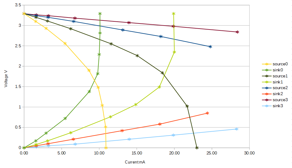
From a different user:
The measurements were made with the following resistances: infinite, 2kΩ, 1kΩ, 470Ω, 220Ω, 150Ω, 100Ω, 47Ω and 0Ω. But for strengths 2 and 3 the minimum resistance was 100Ω.
By measuring into a capacitor, I can confirm that the source and sink current limits for drive strength 2 are about 40mA and for drive strength 3 they are about 80mA. Actually source current limits are a little higher than the sink current limits.
The drive capabilities of the digital-to-analogue converters are very different.
I used it. And it took me hours to figure out, that PlatformIO library manager installed the crappy old v0.92 version, showing it as v1.0.0.
After lots of testing and comparing with arduino IDE i found out, that i was using the old version. After replacing library files with that from author’s github repo by hand, NMEA packet decoding worked smoothly.
Thanks for the explanation, i was wondering what 0x0a means…
Since i use PlatformIO i assume i have to wait some time, until the new espool.py arrives there?
Meanwhile i tested the GPS chip and antenna.
On board is a NEO 6M chip soldered, not a NEO 7M as specified by LilyGo.
But it seems the small ceramic antenna is not as bad as suspected.
I get a fix inside of my rooms and it takes only a few seconds. This is much better than my Garmin Oregon 700 can do.
Below output from two different NEO-6M modules (both labelled NEO-6M-0-001).
The first reports hardware UBX-G70xx the second UBX-G60xx.
And looking at u-center Receiver/Protocol filter only ublox-7 appears to support protocol version 14.
There are fake Ublox GPSs out there, they may work or they may not.
I have come across ones that appear to behave like a normal Ublox but wont accept the standard Ublox confuguration commands. Commands were acknowledged, so not a hardware fault, but not acted on.
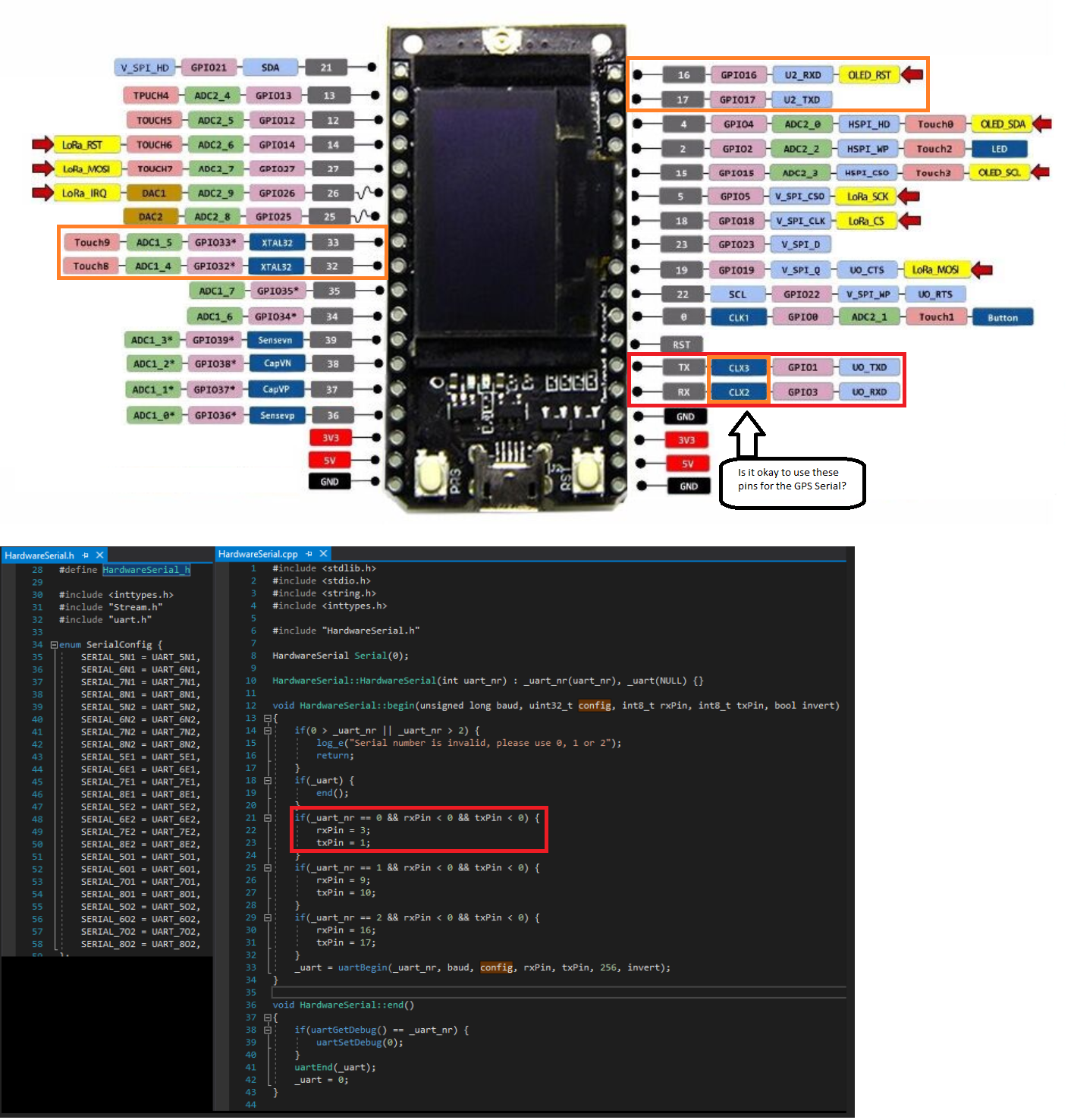
I’m doing a project with the TTGOv1 and I was wondering what the CLX pins do?
For the GPS-module I need to use a Hardwareserial for the TX and RX. Which pins could I use for the GPS TX and RX?
Another Question what is the min. and max VccInput for the TTGOv1?
Congratulations. You appear to have found another error in the TTGO documentation.
CLX2 and CLX3 should be CLK2 and CLK3, or to be more correct: CLK_OUT2 and CLK_OUT3.
CLK_OUT1 to CLK_OUT3 are used as clock out signals for the I2S interface.
Pins can be used for different interfaces. I2S is not used (unless explicitly used by yourself) so you should be able to use the TX (U0_TXT / GPIO1) and RX (U0_RXD / GPIO3) pins.
Is there any TTN Mapper software for ESP32 and LMIC ?
I tried the Draginio TTN mapper but that wont compile for ESP32 or indeed ATMEGA 1284P which was another option I was looking at.
The issue appears to be that the LMIC library mixes data types in a few places; artkey for instance is defined as u1_t and then used in LMIC_setSession() as xref2u1_t.
For more recent Arduino IDEs, I use 1.8.5, the -fpermissive complier flag is not enabled for some hardware type, so the ‘invalid’ conversions cause compiler errors.
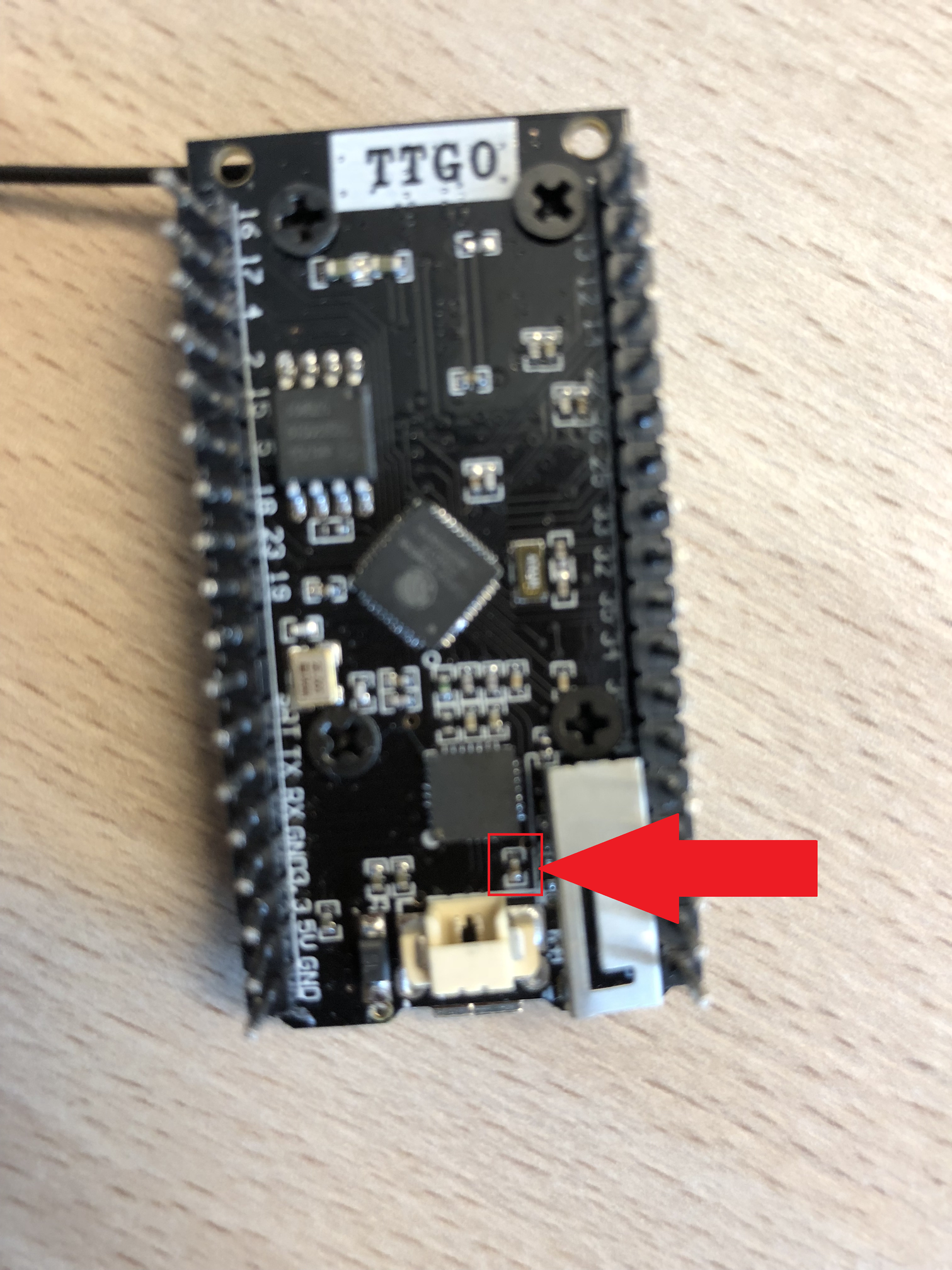
When I was putting on the Batteryconnector I accidently broke the small SMD resistor, it seems this SMD resistor was regulating the power, now the microcontroller is asking too much power. I don’t have any spare SMD resistors. Anyone has any ideas how to fix it, maybe without it? Or is replacing the SMD resistor the only way?
You could search for the schematic diagram of the board and verify the function of that capacitor.
If you break a component it usually needs to be repaired/replaced. Is the PCB itself (soldering pads / PCB traces) still undamaged?
There are no real alternatives, i.e. not reparing (except for replacing the complete board).