TinyGPS++ is a good library for getting data from the NEO6M Chip. I have used that for my mapper shown up in this thread.
http://arduiniana.org/libraries/tinygpsplus/
1 Like
Hi all ,
With the TTGO T-beam I used NeoGps with success .
this library got a very light memory footprint and a good documentation.
But beware the GPS antenna (nice it can be removed) , it have a very poor reception quality.
Meanwhile i checked it:
- DIO1 and DIO2 of LoRa HPD chip are NOT wired to ESP32, but wired to Pinouts “Lora1” and “Lora2”. Connected “Lora1” to GPIO33 and now LMIC works like a charm.
- LoRa HPD chip RST line is NOT connected to GPIO14, but to ESP32 Reset line.
Difficult to see (on my phone) but it looks a passive antenna. In that antenna size the difference in reception quality between active and passive is very substantial.
Whether you can use an active antenna depends on the T-Beam and the Neoblox module used.
Checked the battery monitor on GPIO35: works.
[I][lorawan.cpp:192] onEvent(): Received 2 bytes of payload, RSSI 30 SNR 10
[I][rcommand.cpp:234] get_voltage(): Remote command: get battery voltage
[I][adcread.cpp:19] print_char_val_type(): ADC characterization based on reference voltage stored in eFuse
[I][adcread.cpp:53] read_voltage(): Raw: 2446 / Voltage: 4250mV
[I][rcommand.cpp:242] get_voltage(): 2 bytes queued in send queue
2 Likes
so, soon mobile use of paxcounter (tram, train, Berlin Busses) should be possible…
on the PCB is a U.FL socket. Did not check for what purpose yet.
someone has to enhance the paxcounter code to use the GPS first.
May be to put an external WiFi antenna
Paxcounter support was added for new LilyGo board “TTGO T-beam”:
1 Like
Yes, indeed, the schematic shows it’s connected parallel to the on board “3D” Wifi/BLE antenna. But there is no software switch on board, like the LoPy has. It’s a “0k” resistor, aka solder pad.
yes, it’s called manual soldering iron selection, bit the good news is that we just need to rotate the resistor, sometime you need to cut a wire ![]()
I ordered to TTG Beam here
https://fr.aliexpress.com/item/TTGO-T-Faisceau-ESP32-Sans-Fil-Bluetooth-WiFi-Module-ESP-32-GPS-NEO-6M-SMA-LORA/32873069780.html
Seems to be too fast, I don’t know what frequency it is, I did not had choice to select and no vendors mention it, just taht 2 version exist 433 and 868/915
Any idea?
Of the two commonly used GPS libraries for Arduino, TinyGPS++ and NeoGPS, I find TinyGPS++ by far the easiest to understand and get on with. On very memory constrained systems NeoGPS is worth considering, it can save a hundred bytes or so of RAM, but this is not going to be an issues with an ESP32.
And to second the comment about the GPS antenna, GPS performance is very closely related to antenna size, those tiny ceramic antennas are not so good. And its a good idea to keep GPS antennas as far as possible away from transmitting antennas …
Obviously have a 50/50 chance, that’s not too bad 
ESP32 SENSOR_VP, SENSOR_VN, ADC, Low Noise Amplifier and Touch
If TL;DR, just jump directly to the Questions below (hopefully you can answer some). ![]()
The ESP32 has an integrated low noise amplifier.
It uses:
- SENSOR_VP (GPIO36)
- SENSOR_VN (GPIO38)
- SENSOR_CAPP (GPIO37)
- SENSOR_CAPPN (GPIOIO38)
All of the above input-only GPO’s can be used as regular ADC (analog to digital converter) and as input-only GPIO for digital input.
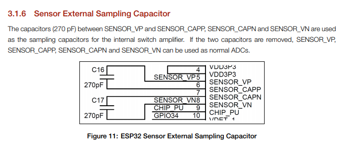
By adding a capacitor between SENSOR_VP and SENSOR_CAPP and adding a capacitor between SENSOR_VN and SENSOR_CAPPN these inputs are configured as low noise amplfier (LNA).
The LNA can measure small DC voltages between pins SENSOR_VP and SENSOR_VN.
When the LNA is used (i.e. the capacitors are mounted) the regular ADC function of all 4 ports cannot be used (the ESP32 Technical Reference Manual V3.3 is not clear about that).
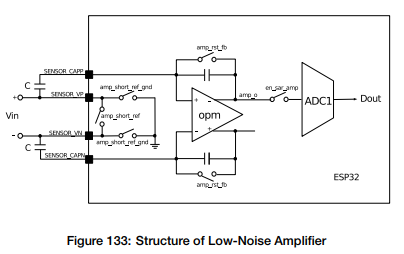
The manual says the gain is configurable by adjusting the value of the sampling capacitors (not really because the capacitors are fixed, but changing gain should be possible via software), and:
- The process is started by en_sar_amp. The amplifier is powered up and connected to the SAR ADC1.
- A pulse on amp_rst_fb resets the amplifier. Vin is sampled by charging external capacitors.
- Finally, amp_short_ref is closed. This starts integrating the Vin sample by the amplifier.
V amp o = Vin · C + Vcm
C is the value of external capacitors in pF. Vcm is the common-mode voltage of the amplifier output, which is fixed (but not further specified).
Unfortunately, the Technical Reference Manual gives very little information about the low noise amplifier and googling for SENSOR_CAPP results in very few hits.
TTGO LoRa32 V2.x
According to their schematic diagrams, on the TTGO LoRa V2.x boards the two sampling capacitors are mounted. Their value is 270pF. It is unclear what the gain of the LNA is.
SENSOR_CAP (GPIO37) and SENSOR_CAPPN (GPIO38) are not available as board pins on the TTGO LoRa32 V2.x.
The TTGO LoRa32 V2 pinout diagram shows regular ADC1_0 and ADC1_3 functions for the S_VP (SENSOR_VP / GPIO36) and S_VN (SENSOR_VN / GPIO 39) pins.
However, according to above link the normal ADC cannot be used on these ports when the capacitors are mounted which is the case so, only the low noise amplifier can be used.
From ESP32 Hardware Design Guidelines V1.9:
The comment “If the two capacitors are removed … can be used as normal ADCs”.
Is not present in version V2.1 of the same guidelines:
From ESP32 Hardware Design Guidelines V2.1:
![]()
ESP-WROOM-32 module
The ESP-WROOM-32 Datasheet V2.5 shows that the ESP-WROOM-32 module has these capacitors (270pF) mounted.
I’m puzzled ![]()
Questions:
-
Are the 270pF sampling capacitors described above required or not (and why)?
-
Are the sampling capacitors required for anything other than the low noise amplifier?
-
Is the low noise amplifier - and therefore the capacitors - required for any internal functionality?
(e.g. for the temperature sensor, the hall sensor, measuring Vdd, touch sensors.) -
If possible, would you prefer to be able to use GPIO36 and GPIO39 as regular ADC’s?
(According to the pinout diagram TTGO LoRa32 V2.x currently has the capacitors mounted.)
According to
and
there currently appears to be no (software) support from Espressif for the low-noise-amplifier.
The lack of support makes me conclude that the low noise amplifier is not used by anyone.
One could wonder why it is still documented in the Technical Reference Manual.
This still leaves the question of the SENSOR_CAPPx capacitors and why they are present on the ESP-WROOM-32 module and on the TTGO LoRa32 (V2.x) modules. Are they really necessary or are they just legacy?
I think i will give NeoGPS a try, since paxcounter is very limited on RAM (since RAM is needed for MACs buffering) and NeoGPS supports the Ublox binary protocol. Thanks for the hint!
Looks like DIO1 wiring is missing again on the board
If you are not much aware of power saving (SPI poll is Ok to you) - you may consider to apply this pull request been developed by Charles Hallard and get rid of any h/w dependency on DIO wiring.
I’ve managed to use this method and it works nicely in my project.
It is worth to mention that the patch is backward compatible with genuine LMIC code - SPI poll is activated only when all of the DIOs are defined as LMIC_UNUSED_PIN.
Looks like DIO1 wiring is missing again on the board
… and they use GPIO12 as Rx from built-in GPS module. Which is generally not good idea because the pin is one of boot-time sensitive “strapping” pins: Home · espressif/esptool Wiki · GitHub
Fortunately, they’ve soldered 1.8V tolerant external flash memory chip (as specified in the schematics), so it should be fine on boot…
2 Likes