What exactly is the question?
The new TTGO LoRa32 V2.1 appears to have the battery connected to GPIO35 via a 2x 100k voltage divider so the actual battery level can now be monitored.
Anyone with a V2.1 who can test and confirm this?
(Still waiting for my board).
I think you are correct that JTAG debugging with the Heltec board is not an option because the JTAG pins have been used for other on-board hardware features.
From ESP-IDF Docs API Guides JTAG Debugging Tips and Quirks:
So apparently JTAG cannot be remapped to other pins.
I am interested in more information about / experience with JTAG debugging the ESP32.
Do you have experience with JTAG debugging any ESP32 boards?
1 Like
I wrote some software to test it, it is included in paxcounter v1.3.71 in branch development of repo. But not tested on the board yet.
TTGO v2.1 running the paxcounter TTN software in an environment with dense footfall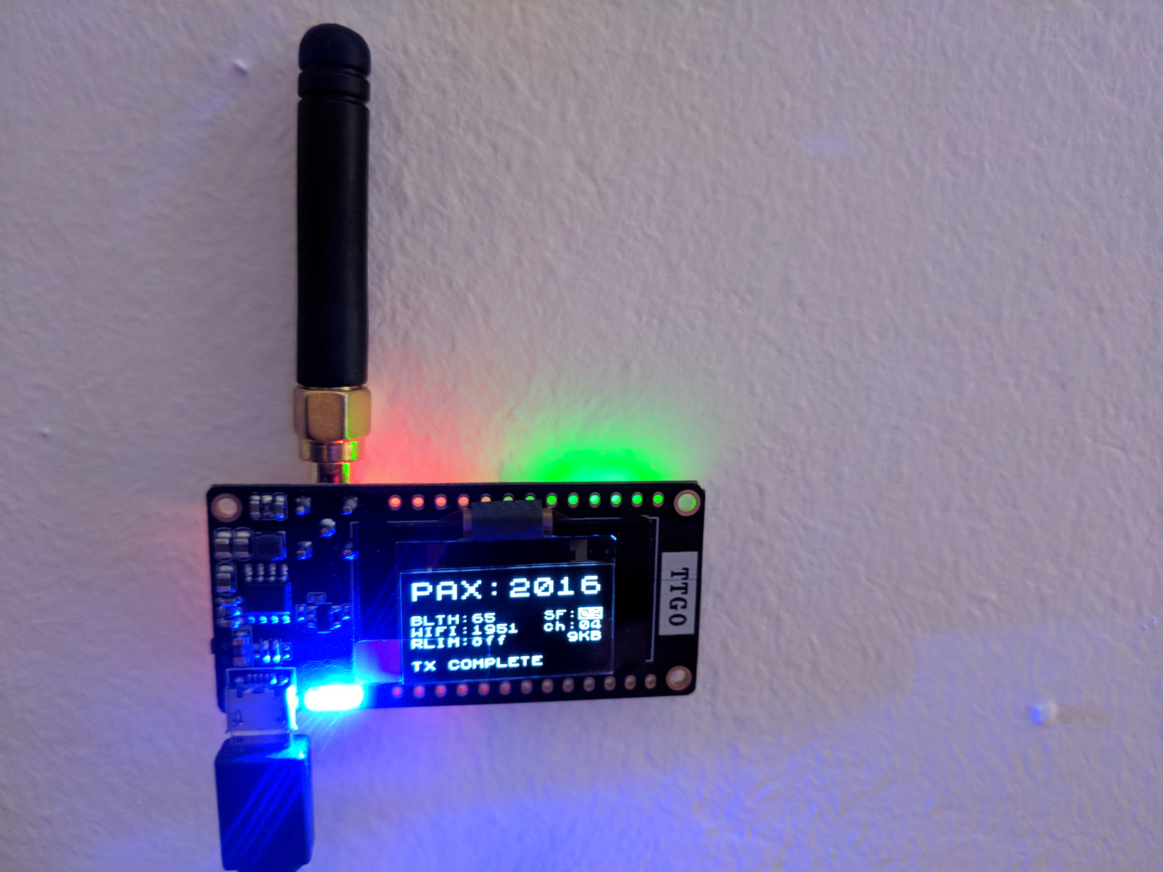
2 Likes
I tried to setup code for reading the voltage on GPIO35 via ADC1 of ESP32.
But i was not successful yet, since i seem always to get the same constant value:
[I][rcommand.cpp:245] get_voltage(): Remote command: get battery voltage
[I][adcread.cpp:31] check_efuse(): eFuse Two Point: NOT supported
[I][adcread.cpp:36] check_efuse(): eFuse Vref: Supported
[I][adcread.cpp:47] print_char_val_type(): Characterized using eFuse Vref
[I][adcread.cpp:86] read_voltage(): Raw: 4095 Voltage: 1082mVFor boards without battery probe: Could this be a way on ESP32 to implement a look-a-like battery voltage probe, only by software, using the GPIO MUX to put internal VRef on ADC input pin?
I got this working now. Needed to increase attenuation of ADC input to maximum (11dB). Now i see decreasing values while operating on battery:
USB power:
4178
4112
Battery power:
3974
3912
3900
3860
3822
This should already be software calibrated Millivolts.
But it looks like these value are too high. Schematic of TTGO v2.1 show a voltage divider of 100k/100k on GPIO35. Maybe the resistors on board have other values?
Next step: check the real voltage on a GPIO35 with a Fluke.
I checked voltage on pin IO35 with my Fluke 77IV multimeter, and compared with the value my software generates: looking good! Voltage divider is at 1:2, as specified in schematic.
| ADC1 | Fluke IO35 | Power | Fluke Batt | Faktor |
|---|---|---|---|---|
| 2082 | 2083 | usb | ||
| 2082 | 2084 | usb | ||
| 1955 | 1954 | batt | ||
| 1948 | 1943 | batt | ||
| 1939 | 1937 | batt | ||
| 1928 | 1929 | batt | ||
| 1909 | batt | 3821 | 2,001571503 | |
| 1903 | batt | 3805 | 1,999474514 | |
| 1899 | batt | 3795 | 1,998420221 |
I tried below simple sketch on TTGO LoRa32 V2.
I connected GPIO35 via 2x 100k (1%) voltage divider (like LoRa32 V2.1) to a an adjustable power supply (instead of battery) so I could do some measurements. Power to TTGO LoRa32 was supplied via USB connector. Voltage measured on the 3.3V pin was 3.287V
I measured the actual voltage on GPIO35 with a multimeter. In contrast to the values measured with analogRead, the multimeter (as expected) correctly showed 50% of the value from the adjustable power supply over the full measured range.
Results:
On average the analog reading on GPIO35 was around 0.2V too low.
Only when the input voltage on GPIO35 approached 3.0V did the difference between actual input voltage and the value reported by analogRead start to decrease.
On 3.0V input it reported around 2.9V. So the difference suddenly started to change here. On 3.30V input the reported value was 3.30V, no differences anymore.
(The measured values did fluctuate, I have taken estimated averages.)
Conclusion:
A constant (about) 0.2V too low from 0 to about 3.0V and from 3.0V the difference quickly disappearing. So there is quite some none-linearity.
#include <U8x8lib.h>

U8X8_SSD1306_128X64_NONAME_HW_I2C display(/*reset*/ U8X8_PIN_NONE);

#define ANALOG_PIN       35
#define ANALOG_MAX_VALUE 4095

void setup() {
    display.begin();
    display.setFont(u8x8_font_victoriamedium8_r);
    display.print("analogRead(");
    display.print(ANALOG_PIN);
    display.print(")");
}

void loop() {
    int analogValue = analogRead(ANALOG_PIN);
    float voltage = analogValue * (3.3 / ANALOG_MAX_VALUE);

    display.clearLine(2);
    display.setCursor(0, 2);
    display.print(analogValue);

    display.clearLine(4);
    display.setCursor(0, 4);
    display.print(voltage);
    display.print(" V");

    delay(1000);
}
This is why i am not just using the arduino analogRead function, but do some more steps to correct raw measurements from ADC:
https://esp-idf.readthedocs.io/en/latest/api-reference/peripherals/adc.html
Step 1: use calibration values stored in efuse of ESP32 cpu:
- using VRef value from efuse, or
- using two-point calibration values
Step 2: do multisampling
- i average over 64 reads
See my code here.
2 Likes
Guys,
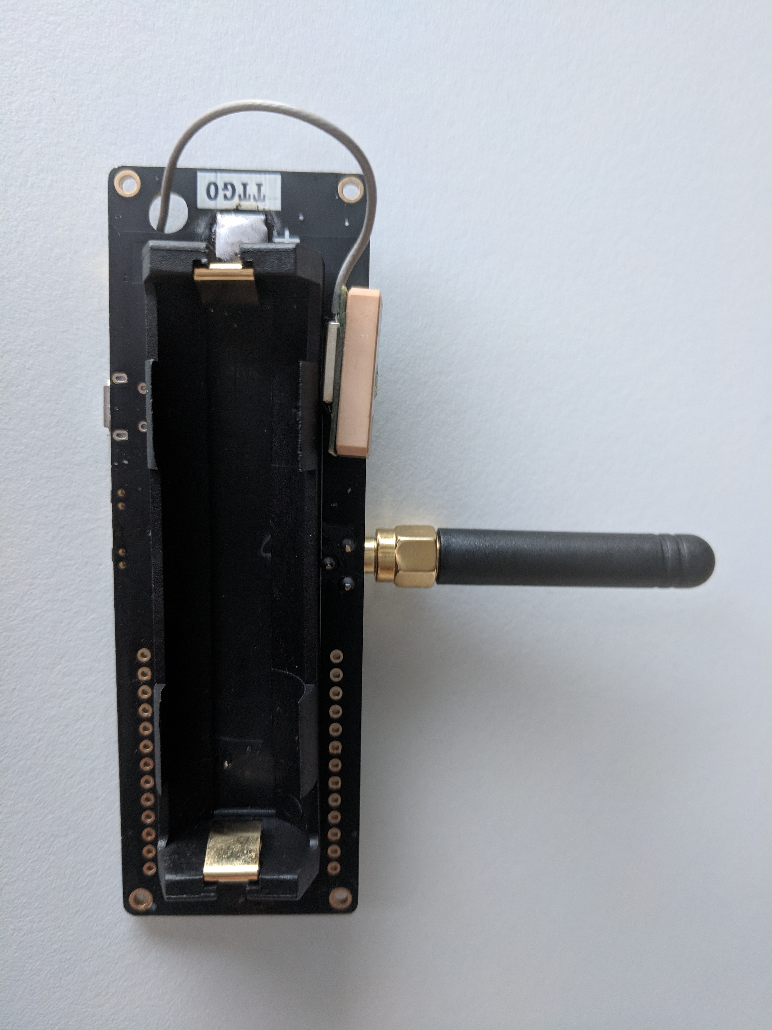
I received these PCB I made, but I have no time for testing, but I can help other way, if you want one, I can assemble one and send it to you @Verkehrsrot or @bluejedi for free 
I know on TTGO V2 version it’s already included but not sure you can disable it to have no drain current, with this one you can, so for even for old TTG version should be perfect, but also for Low Power mode
1 Like

FYI:
TTGO LoRa32 V2 does not have battery connected to a GPIO.
But V2.5 does have it, connected via 2x 100k divider to GPIO35. Fixed, cannot be programatically disabled.
1 Like
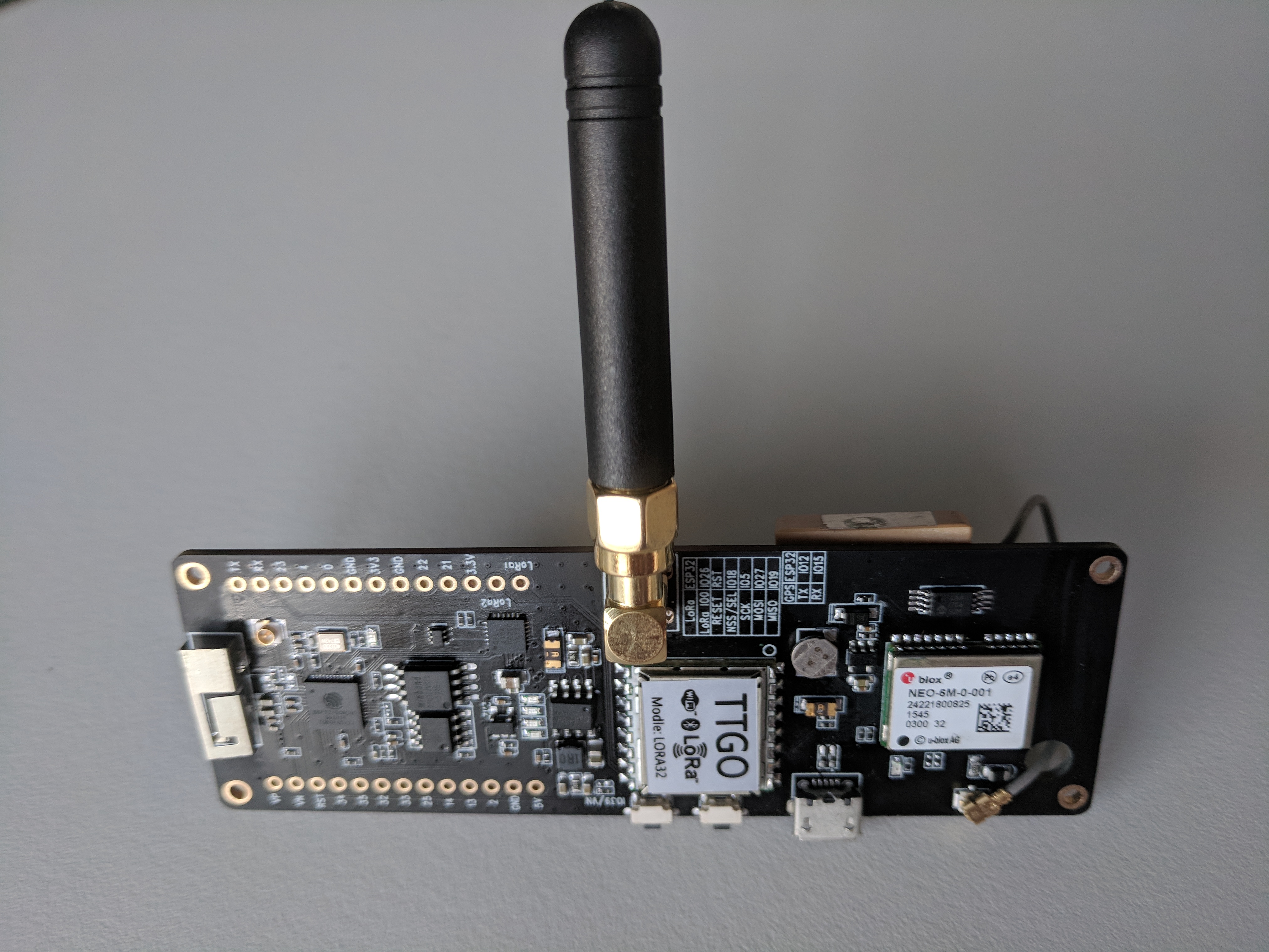
Schematic diagram to new TTGO “T-Beam” module (with GPS) found here
2 Likes
New arrival: TTGO T-beam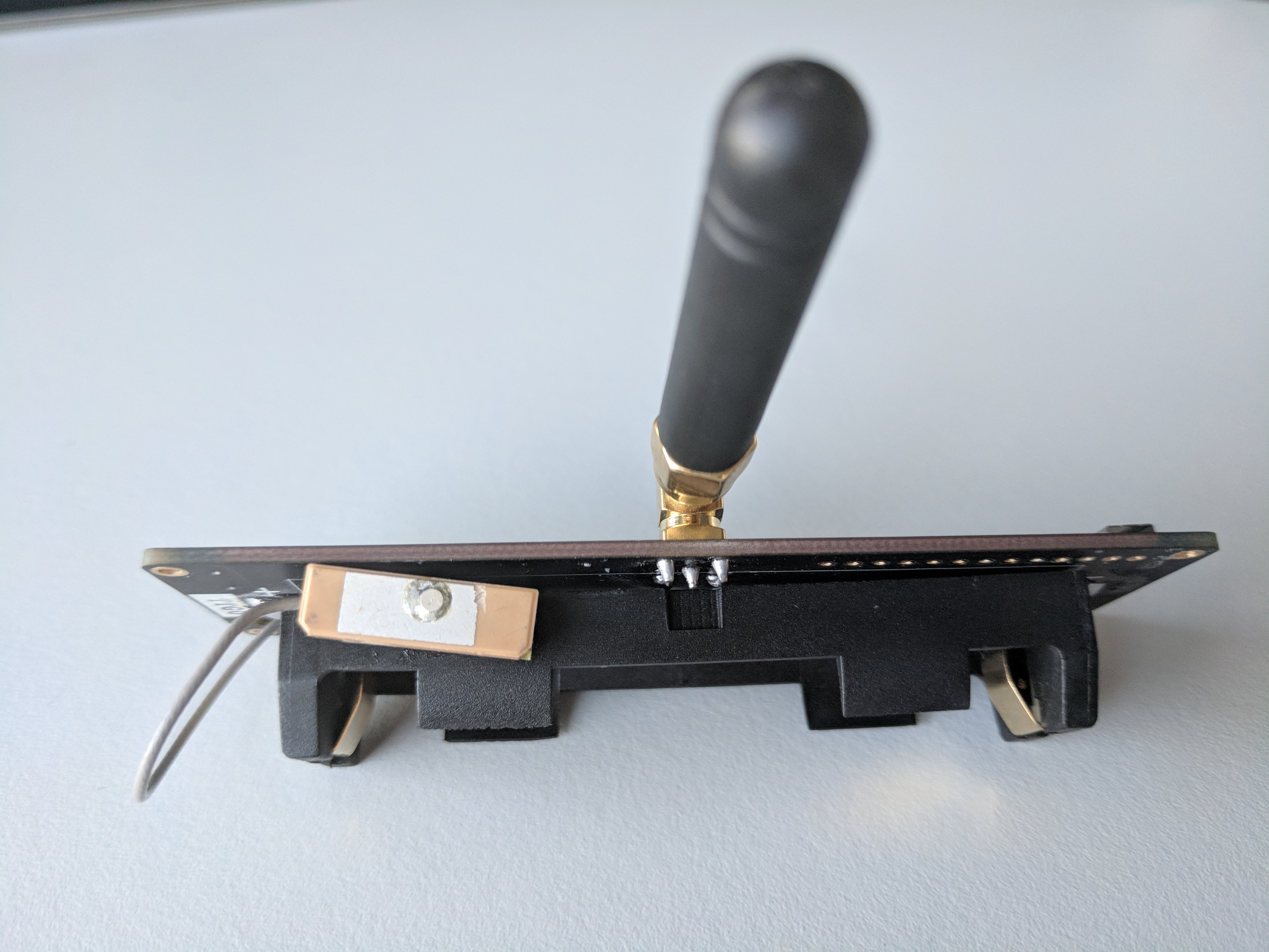
2 Likes
how many do you have now ? 
Chip is ESP32D0WDQ6 (revision (unknown 0xa))
Features: WiFi, BT, Dual Core, VRef calibration in efuse1…3 of each you can find in paxcounter.ini, except LoLin,
Because i test my firmware before i throw it in github.
1 Like
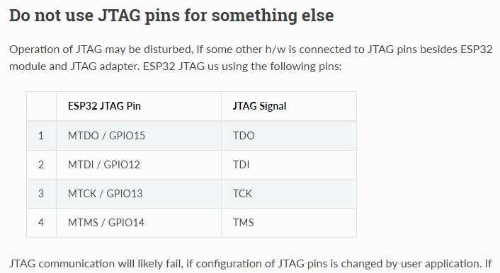
Paxcounter is running on T-Beam.
But the engineer of this board still did not understand LMIC: Device joins via OTAA, but i don’t get “TX COMPLETE” event, what makes paxcounter keep flashing the LED. Looks like DIO1 wiring is missing again on the board 
Did not yet find out how to switch it off, when powered on from battery 18650.
Here’s my ttgobeam.h file:
// Hardware related definitions for TTGO T-Beam board

#define CFG_sx1276_radio 1 // HPD13A LoRa SoC

#define HAS_LED 21 // on board green LED_G1
#define HAS_BATTERY_PROBE ADC1_GPIO35_CHANNEL // battery probe GPIO pin -> ADC1_CHANNEL_7
#define BATT_FACTOR 2 // voltage divider 100k/100k on board
// #define HAS_GPS // to be done
// GSP serial (9600, SERIAL_8N1, 12, 15);   //17-TX 18-RX

// re-define pin definitions of pins_arduino.h
#define PIN_SPI_SS    18 // ESP32 GPIO18 (Pin18) -- HPD13A NSS/SEL (Pin4) SPI Chip Select Input
#define PIN_SPI_MOSI  27 // ESP32 GPIO27 (Pin27) -- HPD13A MOSI/DSI (Pin6) SPI Data Input
#define PIN_SPI_MISO  19 // ESP32 GPIO19 (Pin19) -- HPD13A MISO/DSO (Pin7) SPI Data Output
#define PIN_SPI_SCK   5  // ESP32 GPIO5 (Pin5)   -- HPD13A SCK (Pin5) SPI Clock Input

// non arduino pin definitions
#define RST   LMIC_UNUSED_PIN // connected to ESP32 RST/EN
#define DIO0  26 // ESP32 GPIO26 <-> HPD13A IO0
#define DIO1  33 // Lora1 <-> HPD13A IO1 // !!needs external wiring!!
#define DIO2 32 // Lora2 <-> HPD13A IO2 // needs external wiring, but not needed for LoRaAny suggestions here which arduino core esp32 compatible library i should use for the on board U-Blox NEO 6M GPS chip?