Big ESP32 + SX127x topic part 2

Well, we need a tool here, not a toy.
So, use PlatformIO, not Arduino IDE.

But, of course, you can taylor all the source files and libs by hand to your Arduino IDE and flash the ESP32 this way. That should work, but requires some work. With PlatformIO it’s less than 10 clicks.

Thank you for the tip. Unfortunately, I am getting a similar error, related to the code change:

[I][main.cpp:584] setup(): Features LED OLED
[I][lorawan.cpp:89] printKey(): DevEUI: (removed)
[I][lorawan.cpp:89] printKey(): AppEUI: (removed)
[I][lorawan.cpp:89] printKey(): AppKey: (removed)
FAILURE
lib\arduino-lmic-1.5.0-arduino-2-tweaked\src\lmic\radio.c:696

Well, I don’t know if it’s an hardware problem or just needs some software changes.
These are recent boards I have received yesterday.

I’ll get in touch with ttgo on Aliexpress to see what they suggest.

Fair enough.

I will continue to use my ‘toy’ as will no doubt will many people who participate in these forums.

1 Like

There could be two reasons:

  1. The LoRa chip on board answers with different version than Lmic expects from a Semtech SX1276/1272 chip.

RegVersion: Version code of the chip. Bits 7-4 give the full revision number;
bits 3-0 give the metal mask revision number. Default value: 0x22

The default value is checked by Lmic in radio.c line 694 / 696.

  1. There is no answer from the chip seen by Lmic, causing radio.c to stop. This could be caused by a different wiring of the SPI interface (MISO/MOSI/SCLK) of your TTGO v2.1 boards.

Can you please post high resolution photos of your boards here? Then we can compare.

Another thing what you could do, if you do not worry on health of your board is:

Comment out lines 694 and 696 in radio.c and build the code again.

#ifdef CFG_sx1276_radio
//    ASSERT(v == 0x12 );
#elif CFG_sx1272_radio
//    ASSERT(v == 0x22);

This should not affect functionality of lmic.
Then see what happenes.

Thank you for your suggestions.

I have restored the initial radio configuration in ttgov21.h

#define CFG_sx1276_radio 1 // HPD13A LoRa SoC

commented the whole block in radio.c

/*
#ifdef CFG_sx1276_radio
ASSERT(v == 0x12 );
#elif CFG_sx1272_radio
ASSERT(v == 0x22);
#else
#error Missing CFG_sx1272_radio/CFG_sx1276_radio
#endif
*/

Still not working, now fails in:

FAILURE
lib\arduino-lmic-1.5.0-arduino-2-tweaked\src\lmic\radio.c:550
Which is
ASSERT((readReg(RegOpMode) & OPMODE_LORA) != 0);

As for the boards picture, here it is:

If needed I’ll make new pictures with better lighting and focusing on specific PCB areas.

I’ve tested my 4th and last board, same issue as the 3 others ones.

Cheers.

Looks indeed slighlty different to my one:

  • my one has no print “T3 v1.5”
  • LoRa chip (or only the sticker on the chip?) rotated 180°

IMG_20180613_235149IMG_20180613_235136

Can you check wiring of Lora1 + Lora1 labelled pins to the LoRa Chip with multimeter?

Picture while running paxcounter v1.3.81 compiled IMG_20180613_235830with /hal/ttgov21.h

This looks like a broken SPI connection between the LoRa chip and ESP32 cpu.
Perhaps they really soldered the LoRa chip 180 degrees rotated? That would mean that they don’t test the boards, or test it using a software which has no error handling on the internal SPI interface, just “fire & forget” the commands to the LoRa chip…

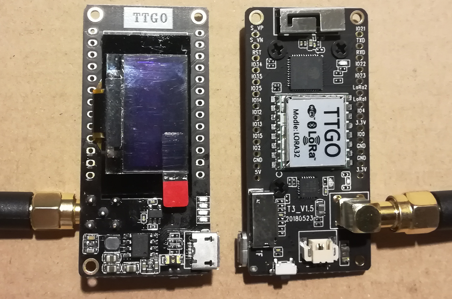
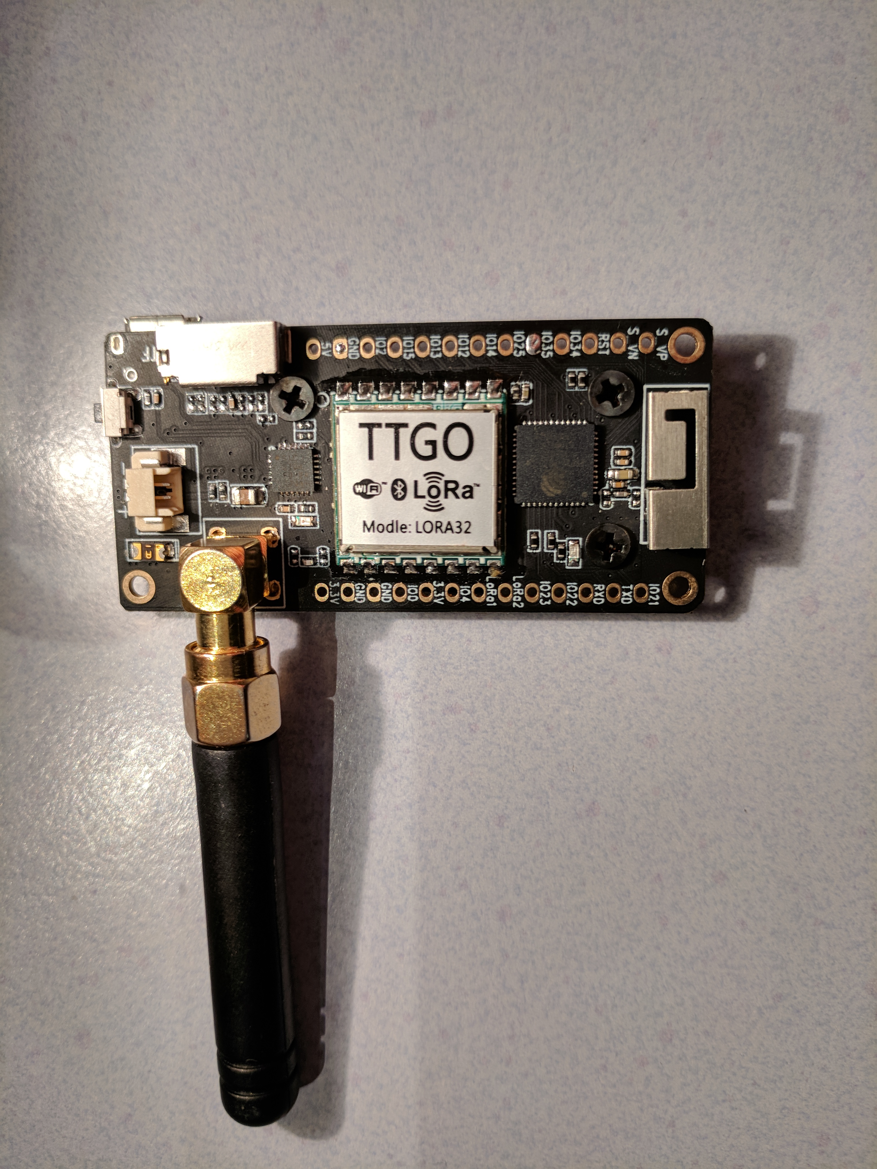
You could validate correct or wrong orientation of the HPD13A LoRa chip on board by tracing it’s GND pins with a multimeter. It has 3 GND pins, see here:

https://de.aliexpress.com/item/CFsunbird-HPD13A-868MHz-SX1276-wireless-transceiver-modul-LoRa-daten-bertragung-SPI-fernbedienung-alarm-Kapstadt/32839694558.html

On the photo it can be seen that the HPD LoRa module is not rotated.
There are gaps in the soldering of the shield. On one (pin row) side there is only one gap. This is also the side with a marker dent on top (not visible because covered by the label). This should be on the same side as the SD card slot. (The shield soldering on the other side of the HPD module has 2 gaps.)

Ok, then probably the pin configuration / wiring of the SPI interface was changed on the pcb.

Again here we see the problems with chinese hardware…

Just checked mine, I have no LoRa sticker at all, so I guess that doesn’t matter too much :wink:

I don’t have any marking on the PCB either (so it is like the one of @Verkehrsrot) and PAXCounter runs fine – Except I can’t get it working on battery, but that’s another story…

not working on battery Does not power on, or does the paxcounter software crash?
(The latter one could be caused by brownout detection, i disabled it for TTGO v2.1, because on my board sample it works without since Espressif 1.0.1)

I meant not powering on.

I even made a short video as everybody keeps telling I am not doing the right thing :roll_eyes:

3 Likes

Nice video, clearly explained.
Looks like a hardware bug. I assume this is independent of the sketch that is running(?).

It could mean that you have a newer (or older) version.
Maybe they ran out and are waiting for the new batch with the spelling error corrected. :wink:

1 Like

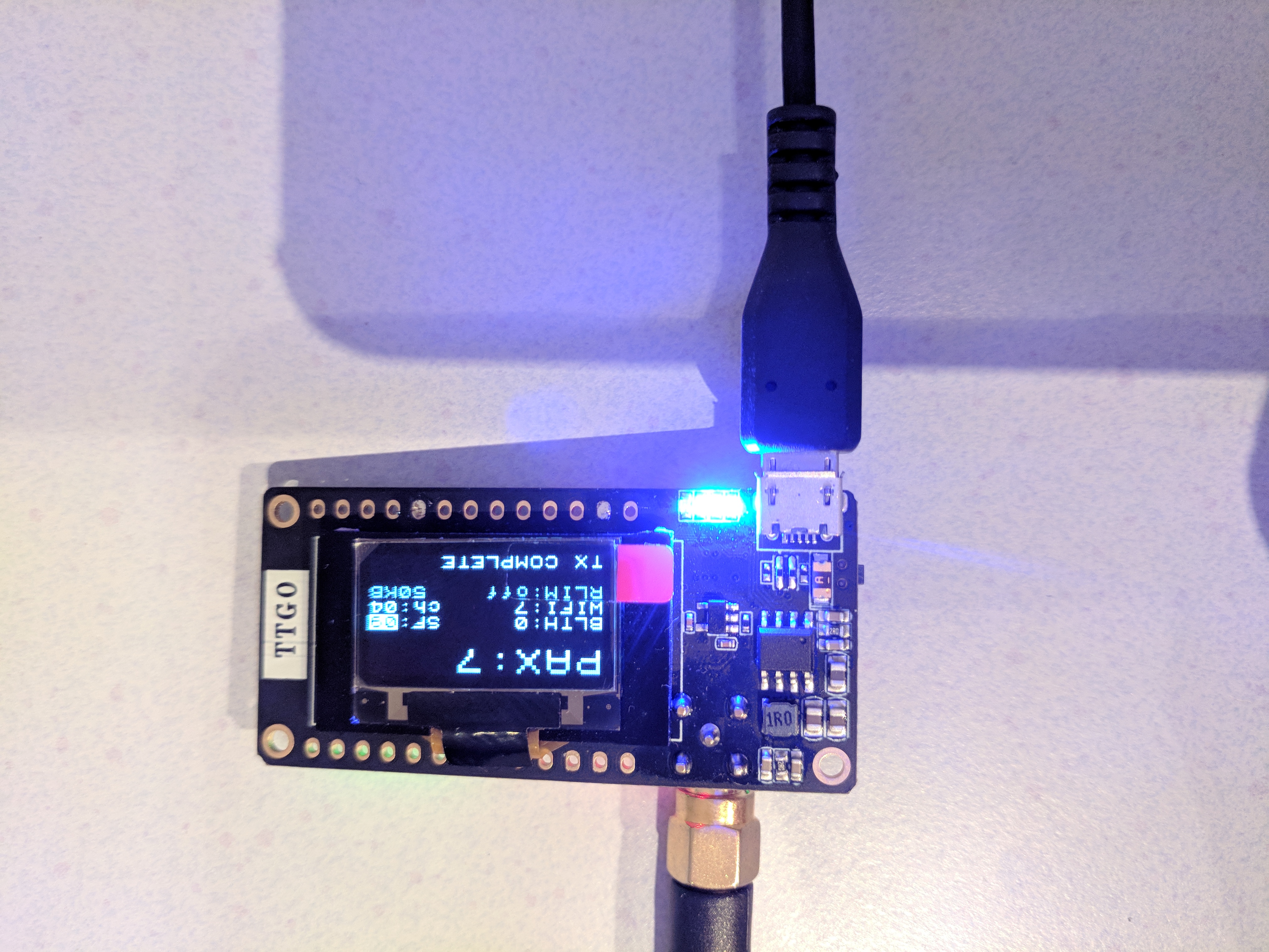
To be honest I haven’t tried any other sketch, apart from different versions of the PAX counter – At this point in time I am new to ESP32, I have more confidence in the PAX Counter than whatever I could write :wink:

If you have some experience with Arduino already you can try some of the basic sketches like blink.ino. They work just as wel on the ESP32 as they do on an original Arduino Uno (or other Atmel MCU’s).

Yep, I have quite some of experience with other MCU (Mainly Atmel and a bit of ARM Cortex), blink should not be a problem – just need to find port :wink:

I don’t believe it will change anything, but it is worth trying