I can confirm that I have the same problem with a blink sketch…
(And as expected the doc is wrong, the led is on 22, not 23…)
I can confirm that I have the same problem with a blink sketch…
(And as expected the doc is wrong, the led is on 22, not 23…)
yes, the LED is on GPIO22, which is also used to clock to the OLED display (D0), so don’t use it, if you use the display.
As expected indeed. Sometimes even after months ‘new’ errors in their documentation are discovered that went previously unnoticed (and so essential that one would not imagine them).
I’m not sure that all TTGO boards come from the same manufacturer. Perhaps there are different version from different manufacturers with different copy/paste bugs on the Aliexpress market…
here is my video:
Did you try it with a real battery, no power source?
The chip which controls the battery management is IP5303.
I did not find a datasheet in non chinese letters yet 
Yes, I actually started testing with the battery. I switched to the power supply afterwards to be sure there was nothing wrong with the battery itself…
Hi!
i also got one of the new boards - with a “T3 V1.5 - 20180523” print on the back.
I also get the same error:
“FAILURE
lib\arduino-lmic-1.5.0-arduino-2-tweaked\src\lmic\radio.c:694”
I am in contact with TTGo (LiLyGo) and after testing wlan functionality of the esp chip, they want me to make a video… “how i use the product”…
What i have tried so far: Blink sketches, they all work. Scanning for wlan networks - ok, checking voltage on the LoRa chip with a multimeter (seems ok), took apart the antenna (they now put a piece of heatshrink on the antenna wire on the inside to prevent shorts due solder) - also ok. Tried flashing the “standard” LoRa send sketch (from the ttgo git repository, for v2 and v2.1) back on, doesn´t work either.
The LoRa chip seems dead… but at least i am not the only one with the problem… 
Hello,
Thanks for your feedback, we are in the same boat 
I am also in touch with Aliexpress vendor since a few days. My test results are the same as yours, LoRa sender code does not work and gets stuck on counter 0 with the TTGO 2.1 device while the same script works perfect (counter increasing) on a TTGO 2.0 device I have.
I haven’t checked the LoRa chip wiring as suggested by @Verkehrsrot but I’ll have a look tomorrow.
Cheers.
News from LilyGo, this might explain the above issue with the LoRa chip:
The LoRa chip of the V1.5 seems dead >>an battery switch does not work
“yes, that is exactly the problem we are >facing at the moment. The Lora_RST pin >of TTGO V2.1 just only be changed from >CHIP_PU 9 to GPIO12 in the V1.5, then the >problem comes up.”
Not sure what CHIP_PU 9 means.
But we know seem to have confirmation that all v1.5 boards are broken. Anyone with an idea how to fix this?
Can someone with v1.5 board to set RST to GPIO12?
After some video exchanges with LilyGo, they offer me to send a new device.
So maybe after having one with a working LoRa but no battery, I’ll have a working battery powered one with no LoRa… 
But at least they seem to care 
On the plus side, the one I have is quite stable with USB power:
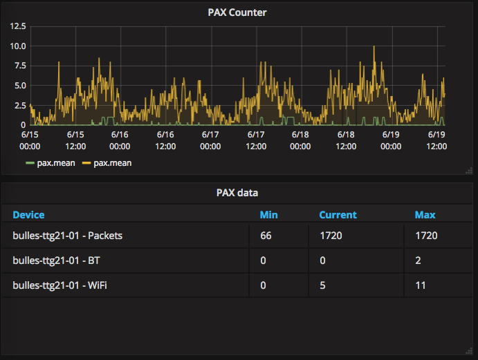
(I am logging the packet counter, so I can see if the board resets)
Nice front end!
Is it cloud based, e.g. grafana?
Can you share code, or put it in the paxcounter github repo?
Tnx!
I have a Node-RED/InfluxDB/Grafana setup. The setup is available here, I forked it from another project but I don’t like too much the way it is setup for what I am doing with it – but it works
I am using Collectd on my gateways to collect gateway data (from collectd directly to InfluxDB), and Node-RED to pull data from TTN and push it to InfuxDB.
Then I am using Grafana for the nice graphs, it is very easy to do.
Putting it all together, for the PAX counter:
I have a simple decoder on the TTN console:
  ...
  } else if (port === 3) {
      // My PAX Counter is on port 3!
      decoded.wifi = (bytes[0] << 8) | bytes[1];
      decoded.ble = (bytes[2] << 8) | bytes[3];
  }
  return decoded;
Then in Node-RED:
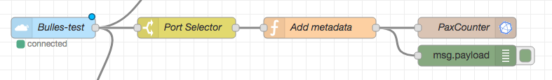
When a message comes on port 3 (Port Selector), I add some metadata and tags:
// Add metadata to the payload
msg.payload['counter'] = msg.counter;
return { payload:
    [
        // Measure
        msg.payload,
        // Tags
        {
            dev_id: msg.dev_id,
            data_rate: msg.metadata.data_rate
        }
    ]
};
And it eventually pushes to InfluxDB the pax table
Grafana is point and click, just select the table and values.
It is probably more difficult to explain it than just do it, maybe I should do a short video to show how it works…
no quality control in shenzen…?
They probably tested with raw LoRa by using the radio head library from github. The LoRa send/receive software which is preloaded on the boards is based on this library, as far as i see.
But for LoRaWAN with lmic a more complex interface to the chip is needed, additonal to raw SPI. I think they did not recognize this.
So perhaps not a QA problem, but copy/paste of reference designs without deeper knowledge?
They literally say: we changed LoRa RST from chip pin 9 which is EN (Enable) (identical to how it is implemented on LoRa32 V2) to GPIO 12. Not clear what is meant with PU (Power Up?).
GPIO12 (SD_DATA2) was used on TTGO LoRa32 V2 for SD card interface (4-bit SD IO). The same pin is also part of the JTAG (TDI) interface.
In what way ?
I thought that all LMIC required, in addition to the standard SPI pins, was access to DIO0, DIO1 and DIO2 ?
Any tips for good ESP32 /lora combo’s that play well with deep sleep e.g. in the uA regions?
I have not seen them anywhere here yet. Current versions of Heltec and TTGO ESP32 LoRa boards were not designed with low power in mind (their designs currently are not sophisticated enough).
Room for improvement.
All have LoRa and OLED display (and battery monitor divider resistors on models where present) permanently powered.
The LoRa module does not draw that much power when in sleep mode IIRC but I haven’t done any exact measurements yet. Others may have more info on this.
I tested 2 SSD1306 OLED displays (similar to the one on the TTGO and Heltec boards). Some simple tests for a weather station node (temperature, humidity, barometer and light. Using U8x8 library with 5 Lines of text on the display.
Display A used 4.4 mA when on and 7.3 uA when in power save.
Display B used 3.3 mA when on but 33.0 uA when in power save.
Quite a big difference. I think the 7.3 uA is quite acceptable for some off the shelve general purpose hardware but 33 uA much less so.
LMIC uses DIO0 and DIO1 for LoRa, for FSK it uses DIO0 and DIO2.
So for LoRa you only need DIO0 and DIO1.
LMIC is a LoRaWAN stack, if you only test the LoRa radio with a limited amount of DIO port(s) then it is possible to miss issues that only arise when using LMIC and LoRaWAN.