I have not seen a commercial product, but I have my own ESP32 board that goes down to 8uA in sleep mode, thats with a LoRa device and SD1306 display.
What LoRa module are you using?
Does the board support battery monitoring?
Do you switch off power of LoRa, display, battery monitor (even the ESP32 maybe) for sleep?
The LoPy4 module. Can be programmed in Python, however you’re free to use C as well.
exactly. What means that these Pins need to be wired.
exactly. LoPy4 draws less power than all Heltec and TTGO china boards 8 have metered. But it’s not real Low Power hardware like e.g. the Nexus from Ideetron (not ESP32), because the peripherals cannot be consequently switched off.
The LoPy4 does not have a display (so does not drain power because it cannot be switched off). This can make a significant difference for low power.
What LoRa module are you using?
RFM9x or Dorji DRF127x, on a plug in Mikrobus module.
Does the board support battery monitoring?
Yes at the cost of around an extra 3uA.
Do it switch off power of LoRa, display, battery monitor (even the ESP32 maybe) for sleep?
All except the battry monitor.
One issue you need to deal with when the ESP32 is put into such low current sleep mode is that all the IO pins are turned off, so you need some external pullups.
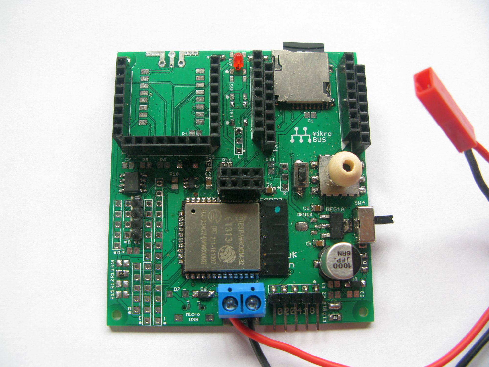
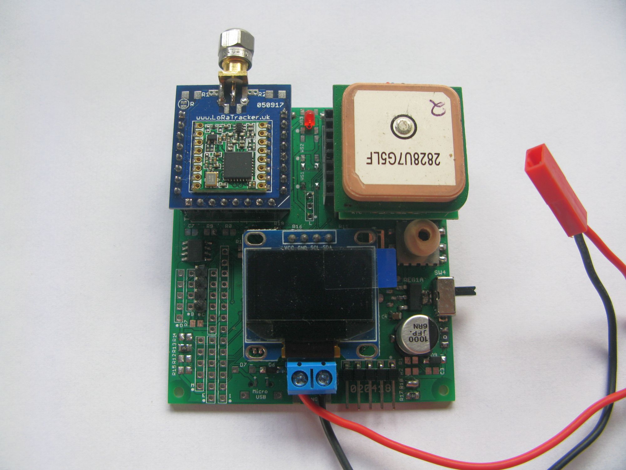
Here is the prototype board, there is a rev 2 on the way. The initial choice of regulator was OK for circa 250mA and had an IQ of around 1uA. But it could not cope with the WiFi switch on. I eventually found a replacement, which was fine on the breadboad and its been incorporated into the rev 2. Its the size of, and is powered by, a 4 x AA battery box.
The board uses Mikrobus sockets so you can easily re-purpose it, change LoRa modules add a GPS etc. It has a FRAM and TC74 temperature sensor on board.
1 Like
How do you get 3 uA for your battery monitor? Using a 2x 560k resistor voltage divider?
Can you be more specific on “all IO pins need to be turned off, so you need some pullups”?
The component in the middle right (with white round part with a whole) is the temperature sensor?
Something like a 1M and 100K divider, with a capacitor across the 100K, you do loose some precision, but we are only measuring the battery voltage, its not critical.
The component with the wooden bead on the top is actually a navigation switch, it was a bit fiddly to use so I replaced it on V2 with some push buttons.
Can you be more specific on “all IO pins need to be turned off, so you need some pullups”?
I actually said;
all the IO pins are turned off
Thats what the ESP32 does in deepsleep, it turns off all the IO pins. This causes problems with the LoRa device in particular as now SCK, MOSI, MISO and NSS are floating, which is bad if you want low current mode, so you need to add external pullups to these pins.
Hi all ,
Let’s start with a big thank for all the informations available in this forum.
For my work ( a big construction company) we need to equip our construction machines with small geotracking device.
all the tests went well so far
(Testing with private lora gateway from Matchx and Lopy+pytrack from Pycom ).
But now I need to go with deepsleep issues…
We only need to ask server once an hour if the machine need to be localized ( if so , we activated the GPS chips) , the rest of the time is deepsleep and actual solutions i tested are not optimised ( as show some posts before ).
So i start thinking to my own board for prototype.
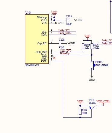
The idea here is to use a very low consumtion RTC to drive ESP32/lora and GPS chip.
ESP32 Will send the next start time via I2C bus and then ask the RTC to shut down the power.
i find that RV-1805-C3 from micro Crystal can be a good competitor ( 60nA , power management with power switch )
RTC link
i just done some shematics , but before going any further I just want to know is anyone have tested that before and have some suggestions to make ?
here is how the RTC will be connect ( the VDD_CTRL will drive ESP/lora power )
Thanks in advance , and sorry for my poor english ;D
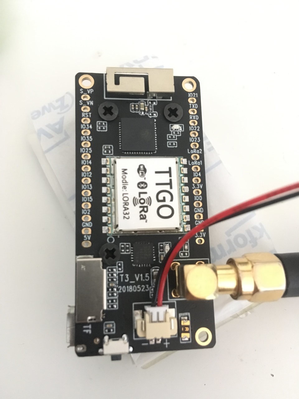
So for everyone with the new TTGO v2.1 and this error with paxcounter:
“FAILURE
lib\arduino-lmic-1.5.0-arduino-2-tweaked\src\lmic\radio.c:694”
If you change the RST Pin definition in the ttgo21.h file, it works…
from:
#define RST LMIC_UNUSED_PIN
to:
#define RST GPIO_NUM_12
2 Likes
- Do you mean that you need pullups only on ESP32 IO ports that are connected to the LoRa module?
- This is needed for the LoRa module (not the ESP32)?
- This matters for when the LoRa module is powered off? (assuming you power LoRa off before putting the ESP32 into sleep.)
- Not needed for LoRa RST and DIO pins?
So LoRa RST is verified to be on GPIO12 now.
This is for the TTGO v2.1 with V1.5 marked on the PCB, is that correct?
(Other revisions will probably follow.)
Do you mean that you need pullups only on ESP32 IO ports that are connected to the LoRa module?
Only ones I needed to add, but potentially any pins that are connected to another device.
I have not checked that the SD card can be powered down effectivly, it would be very useful for logger applications if it can.
This is needed for the LoRa module?
Yes
This matters for when the LoRa module is powered off?
Yes, when the LoRa module is put to sleep, its not powered off as such.
Not needed for LoRa RST and DIO pins?
RST has its own internal pullup, the DIO pins in LoRa mode are normally outputs.
In your previous answer you said that you are powering off the LoRa module:
This somewhat conflicts with:
So you actually do NOT power off the LoRa module but only put it to sleep?
(Physically powering off the LoRa module does not gain substantial power saving?)
So the only component that you DO switch power off before ESP32 goes into sleep is the SSD1306 OLED display and you still manage to get only 8 uA usage in sleep, is that correct?
Yes, its the 1.5 Version, it also has a date next to it: 20180523
3 Likes
Sorry for the confusion, I did not physically remove the power from any device, including the SSD1306 OLED.
As you will realise physically removing the power from a device can cause problems because input pin protection diodes can then effectivly pins to ground.
This really makes me curious how you get a result off only 8 uA in sleep.
3 uA was already eaten by the battery monitor resistors, so that leaves 5 uA for ESP32 in sleep, the display and the LoRa module.
I tested two SSD1306 displays. One used 7.3 uA in power-save mode and the other used 33 uA in power save mode. In my case that would leave only 0.7 uA for the ESP32 and the LoRa module when using the most power-save friendly of the two displays (the other one eats 4 times 8 uA just for the display alone).
(Most power-save friendly because when not in power save it uses 33% more power (4.4 mA total) than the other display (3.3 mA), so under normal use the other display is actually more power friendly.)
I do not have experience with this, but IIRC I have seen others switching off power of components when they need to save power for ultra low power applications.
Maybe they vary a bit then, mine went down to next to zilch with this code;
esp_sleep_enable_timer_wakeup(TIME_TO_SLEEP * uS_TO_S_FACTOR);
Serial.println(F(“Start Sleep”));
Serial.flush();
disp.clearDisplay();
disp.display();
disp.ssd1306_command(SSD1306_DISPLAYOFF);
esp_deep_sleep_start();