Ordered one. Interested in the deep sleep possibilities
Peter,
The LoPy runs a variant of MicroPython. The guys at Core Electronics have them running LoRaWAN, so porting their libraries to ‘generic ESP32’ may be worth looking at.
Dave
I later found that the packets were getting through… with some odd delays, e.g. between 16:51 and 17:57.
I’m looking into the serial logs…
Dave
Hi Dave,
Thanks for that.
I am familar with Pycom. I am using Lopy4 and FiPy in some projects.
I have seen someones attempt to use the lorawan library code (ex arduino) and port this across to micropython and TTGO, but have not been able to get full details yet. I need a piece of pre-packaged code that I can just install on the TTGO. My experience at building such is not good.
Peter.
Seems to me you’re using ABP, and are sending about every minute, and then restarted the node at 16:51? It then took 56 minutes to re-use counter values 0 through 56, which TTN already handled, so ignored. Somehow 57 was lost, so 58 was the first that was accepted. See the documentation and ABP node stopped working -> Fixed by creating new ABP.. Why? :) - #7 by arjanvanb
The current draw in deep sleep is disappointing (high). These boards are not suited for low power operation.
Don’t use APB. Use OTAA.
APB did also give me lot’s of problems. Messages not coming true, delays etc.
Thanks Arjan,
I’ll read the documents:-)
And learn from it.
very dissapointing then.
Perhaps it is a good idea to see if we can come up with a crowdsourced breakout board to use an RFM95 with any of the ESP32 boards that work well on low power. With a wemos d1 mini / RFM95 combo with one of Charles Hallard’s breakoutboards I got down to very low (<mA) figures. Would be nice to get such figures from the ESP32’s as they have great abilities for deep sleep (longer than an hour), interrupts and the ULP processor.
Perhaps Andreas Spiess’ overview of current ESP32 offerings is a good starting point:
Off-topic, but: ABP should not cause “lot’s of problems”. The only problems ABP might give you, which OTAA does not:
- The need to reset frame counters when restarting a device. (Reset automatically for each OTAA Join Accept.)
- The need to program the network settings into the device. (Set automatically in an OTAA Join Accept.)
- Vendor lock-in to a specific network provider. (An OTAA node can join any network in its region, if you can make it perform a new OTAA Join when needed.)
So yes, OTAA is to be preferred (though it might be hard to join, if downlinks are not working), but once a node has succeeded an OTAA Join, it’s behaving exactly the same as an ABP node. On the other hand: if you’re doing an OTAA join very often, you might run out of nonces. So, for both ABP and OTAA, one should persist the node’s state if that’s not preserved when sleeping.
2 Likes
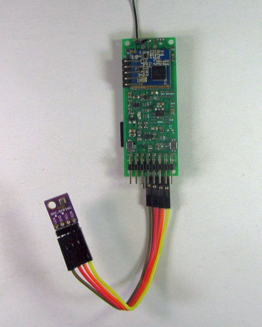
I just finished a ESP32 based version of one of my tracker boards, based on LoRa DRF127x and with connections for a GPS and a couple of I2C sensors or displays, sleep current in non WiFi mode is 11uA. If you want to use the ESP32 WiFi you need to use a different regulator and sleep current rises by 25uA or so.
2 Likes
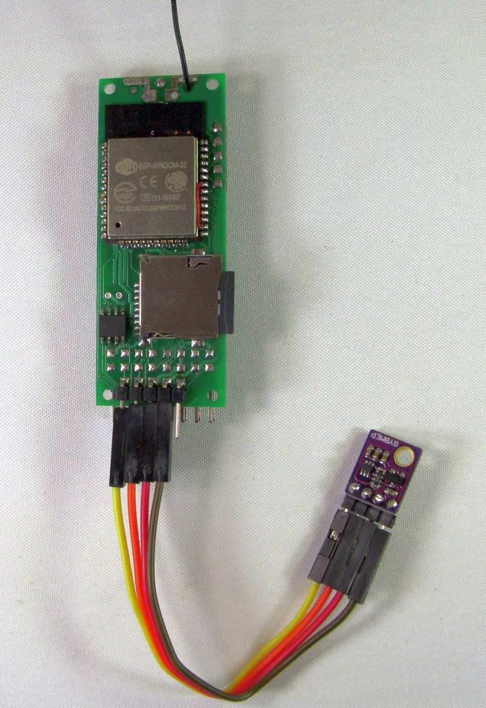
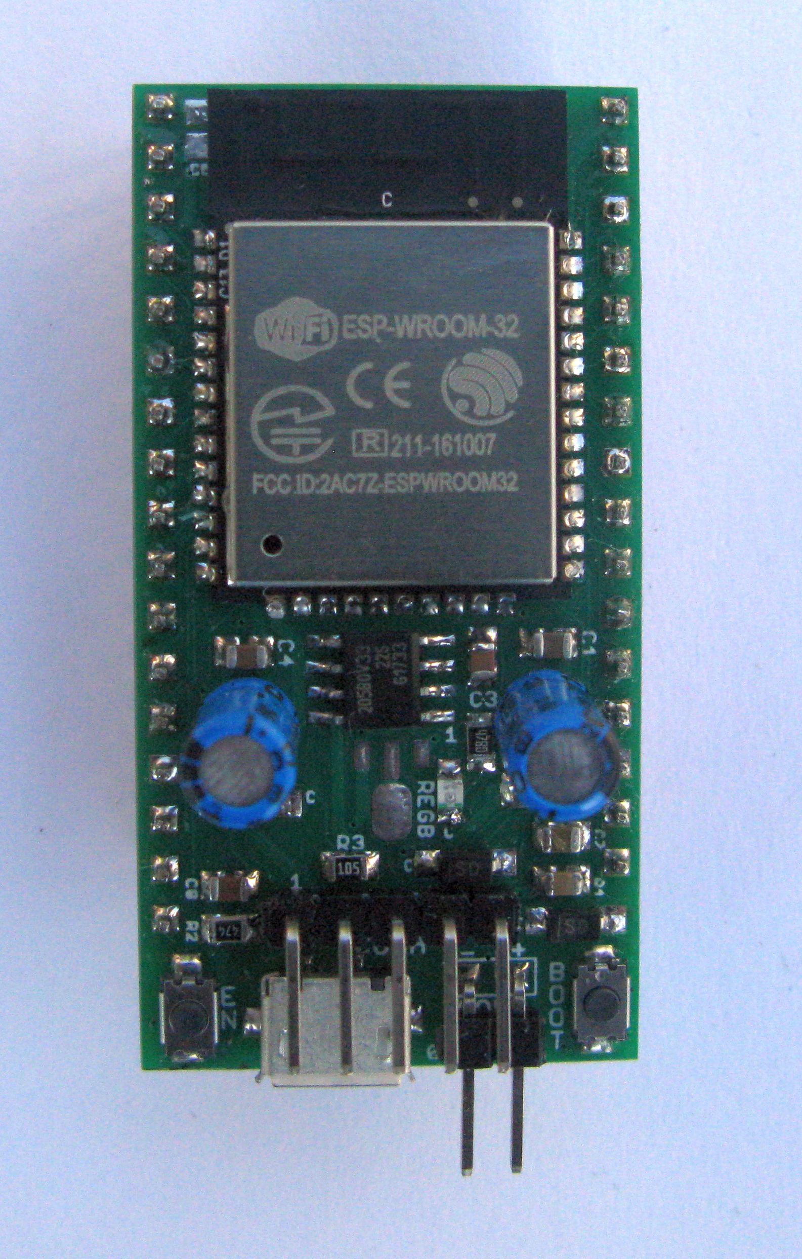
If anyone is interested in DIY and exploring low current standby of the ESP32, I have a number of the boards below you can have at cost + postage.
It can be powered by USB or battery with a choice of regulator. MCP1700 for a total sleep current of 11uA, or the SOIC regulator shown for a sleep current of 38uA. The SOIC regulator will cope with the WiFi switch on pulse.
No USB to serial converter on board, hence the very low sleep current. Program with a standard low cost USB to serial adapter.
3 Likes
I now realize that charles hallard has already done so months ago. Are there recommendations for esp32 / rfm95 breakoutboards that do not use the mini flowed capacitors, solder friendly?
Are you building your own ESP32 board ?
If its a ready built ESP32 board you are buying, why would the particular capacitors it uses be of concern ?
What I meant was an RFM95 breakout board. Just found the full topic here (Designing a breakout board for the ESP32 / RFM9X) that I had missed. Apologies!
Just a followup.
I have edited my lmic_as923.c to make both the default channels F1, and now I’m not missing every second one.
I’ll put it back to be standard.
Dave
Attention users of TTGO21 v1.6 (boards labeled “T3_V1.6” on pcb): During a test run on battery after about 30 minutes the battery exploded and got on fire. Board and battery burned down to nearly nothing in less then 30 seconds.
I used a Li-Po battery 3,7V / 840mAh. It was properly connected to the board, since the board did boot and run on battery. I then connected the board additionally to a 1A USB wallcharger using it’s USB port.
Since there is nothing left after board and battery burned down, i cannot investigate what happened.
But i remember that i wondered about the voltage measurement which was shown by my software, using the voltage divider on board: It showed 5,024 Volt. If this is really correct - and i assume it is - it means that there must be a hardware design error on the board which is causing a direct connection of the battery to USB 5V.
5 Likes
or the protection circuit failed or was not even there … but you cannot ever charge a lipo with more then 4.25 volts, could be a faillure in the dc/dc to
I used a Li-Po battery 3,7V / 840mAh. I then connected the board additionally to a 1A USB wallcharger
using it’s USB port.
If the power/charging circuit is designed similar to the Adafruit Huzzah32 then in this configuration the battery is being trickle charged (hopefully with a charge current <= 500mA) if you hooked it up via the JSTPH2 connector, and the board is using the power from the USB, right? Also the voltage measurement (on the voltage divider) is that of the USB power (not the battery) if the USB cable is connected; I also got that on the graph.
The only battery problems I have encountered was when connecting unprotected Lifepo4 batteries using the JSTPH2 connector and powering the board using the USB cable. Then the board tries to charge the battery up to 4.25V which is a problem if the LiFePO4 battery does not have a protection circuit. I lost a few batteries because of that (but none started to smoke).
Perhaps it was a short in the battery itself. I hope ![]()
I can confirm. The TTGO V2 1.6 (T3_V1.6 20180606) goes down to approximately 8 mA current in deep sleep (measured with 4AA powering 5V via normal multi meter). It seems the OLED stays powered on while the ESP32 goes to sleep. Will try and see if powering down the OLED is possible (seems possible in the UG2 libraries, but this will take me some effort in rewriting my code from SSD1306 unfortunately).
Looking at the result achieved here: https://bengoncalves.wordpress.com/2015/10/01/oled-display-and-arduino-with-power-save-mode/ I hope to be able to bring the deep sleep power consumption down to less than <1mA.