Big ESP32 + SX127x topic part 2

When you connect the board, do you see the COM port appearing in Windows Device Manager?

Do you have any other board with CP2102 USB to serial chip? Does that serial port work OK?
You could try to (re)install the CP2102 serial driver (I have no link at hand).

Have you selected Heltec Wifi LoRa 32 as the board?
You could try to manually update the ESP32 Arduino Core (if you are using Arduino IDE).

Try with the standard Blink sketch to keep things simple while troubleshooting.

1 Like

I could solve this. As always failure was on my side:
I set RF output in radio.c to pin RFO of SX1276, not to PA_BOOST.
But TTGOv2 needs RF-power at pin PA_BOOST, otherwise the module shows no RF output.

We really need the schematics from lilygo for this module… :face_with_raised_eyebrow:

1 Like

It seems you’re using Espressif 8266 platform:

Heltec and TTGO boards use Espressif ESP32 CPU, not 8266.

Not sure if this makes a difference here, but try to use ESP32 platform and use esptool.py for uploading the binaries.

3 Likes

You saved both me and the board bluejedi. The problem: My Arduino IDE SW was not updated, so when I first selected the board it never popped up among the selectable ones. I think I used ESP8266 board instead (as Verkehrsrot also commented on in a suggested solution). Anyway, I did a fresh Arduino install and then the board popped up and now it works as expected. Thanks a million for the help. :smiley:

2 Likes

Hi, I just received my RFM95W LoRa Radio and I’m planning to connect it to my Heltec ESP32 with LoRa. I bought the module since my Heltec board only has 433 MHz. Can someone help me to setup the device? According to the source code on LMIC I have to setup the lmic_pins. However, I don’t know which pins I should set here. Hehehe any help would be much appreciated
image

ESP32 LoRa board Challenge: Heltec, TTGOv2, Pycom Lopy.IMG_20180210_164934

1 Like

My money is on the Pycom Lopy which has the better antenna.

2 Likes

After only a few hours of testing i can confirm: Pycom LoPy ist best deal.
Forget that china boards, you save some bucks but have lots of trouble.

But what happens if you just put the LoPy Antenna on one of the cheap boards?
Because the China boards + a Pycom Antenna are still (much) cheaper than the Pycom configuration that you’ve got.

Note: I’ve got both (the LoPy as part of the Kickstarter), I like the Pycom quality, their support etc.
Just pointing out that the cheapest reliable solution might be a mix of parts sourced from different venders.

My guess is that TTGO V2 will have the best LoRa performance of the Heltec and TTGO boards because its use of standard (shielded) HPDtek LoRa modules. Combine it with a good antenna (can be had for €3) and you probably have a nice combination for prototyping.

Andreas Spiess has already ordered a TTGO V2 for testing with his spectrum analyzer. Let’s hope he can manage to show the results of that in a video any soon (hopefully within weeks, if not we just will have to wait longer).

2 Likes

But the testing on the spectrum analyzer showed only that the antennas were wrong/useless, so it just as well can be that the V2 has the same incorrect antenna.

Aliexpress has those for that price, but without the equipment that Andreas has, or the option to test them like that, how would we now if any antenna bought there actually is good for 868Mhz?
(field testing and comparing to known nodes/antennas being the only option, but you would have to have at least 1 good reference antenna).

Early test results:

  • TTGOv2 using the same included rubber antenna as Heltec is ~5dBm better on LoRa 868 MHz.

  • The “3D” Wifi antenna of TTGOv2 works better than the Heltec’s coil, but it’s not as good as the LoPy’s onboard ceramic wifi antenna.

  • Unfortunately the TTGOv2 module resets after tx’ing ~200-250 packets for unknown reason

Test setup:

  • LoRa: send packet all 4 minutes, compared receive results on two gateways (one in 5m distance, second in 2km distance)
  • Wifi: continously scanning and counting MACs seen in the air, using monitor mode of ESP32, comparing the cumulative count
  • Same software on all 3 boards: c++ code, using arduino-esp32 framework v0.12.0 and LMiC 1.5 arduino-2
  • On TTGOv2 DIO1/2 of HPDtek module externally wired to GPIO33/32 of ESP32

Power consumption, during active wifi scan, no LoRa TX’ing, OLED display off, 5V USB powered:

  • Heltec ~650mW
  • TTGOv2 ~670mW
  • LoPy with expansion board: ~530mW
  • LoPy pure, without expansion board: ~460mW

Result overall:

LoPy wins, 30% less power consumption with 100% same functionality.
Heltec is stable but on the RF side not as good as TTGOv2.
TTGOv2 seems to have solved the issues of TTGOv1 on the RF side, but seems it does not run stable.

1 Like

You can get antennas from here:
http://www.rocketscream.com/blog/product/ism-band-3-dbi-dipole-antenna-straight/

1 Like

This is the antenna that was included with both my TTGO LoRa32 V2 and my Heltec Wifi LoRa 32 boards (868MHz versions).

The Heltec antenna is 2mm shorter. This could either be by design, a production error or (non) ‘acceptable’ production margin.

See here for picture and details: The BIG and SMALL ANTENNA topic part 1

See The BIG and SMALL ANTENNA topic part 1 for a cheap 868MHz center-fed dipole whip antenna, SMA, 19,5cm (adjustable).

I use this antenna for the gateway too.

(RAK831 RPi gatewa. Note: RAK831 uses RP-SMA instead of SMA but I replaced the onboard connector. The same seller also sells the antenna in a RP-SMA version).

Hi,

This is my first post to this forum :grinning:
I really enjoy all the informations collected here : thanks for that.

I did follow a lot of this topic, together with Andrea’s review of the ESP32 ready made boards and their quite poor design…
So I decided to build my own, and as you will see it is really easy !

take an ESP32 Lolin lite V1 board
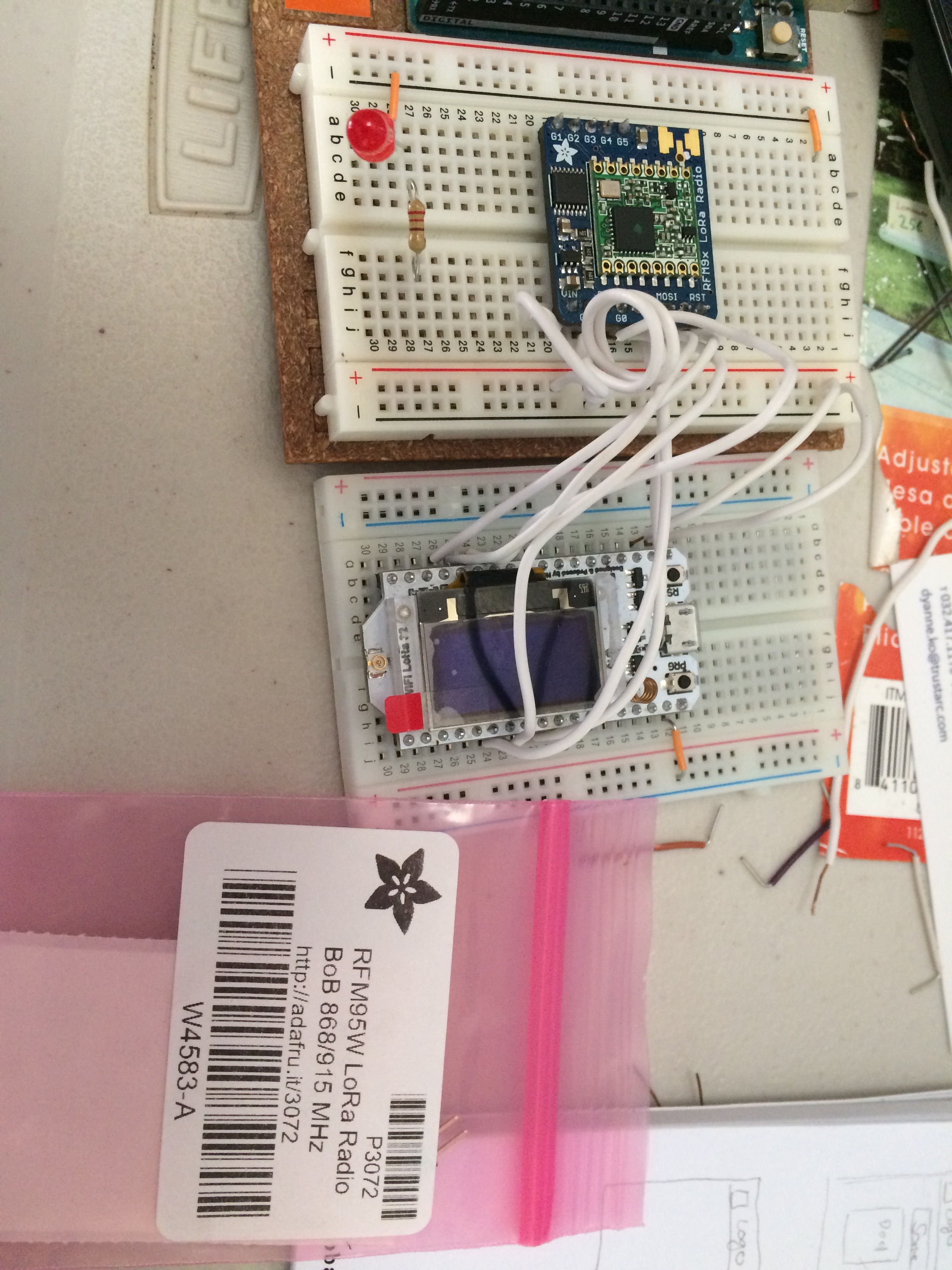
take an RMF95W lora module
take a Hallard’s shield for hopeRF
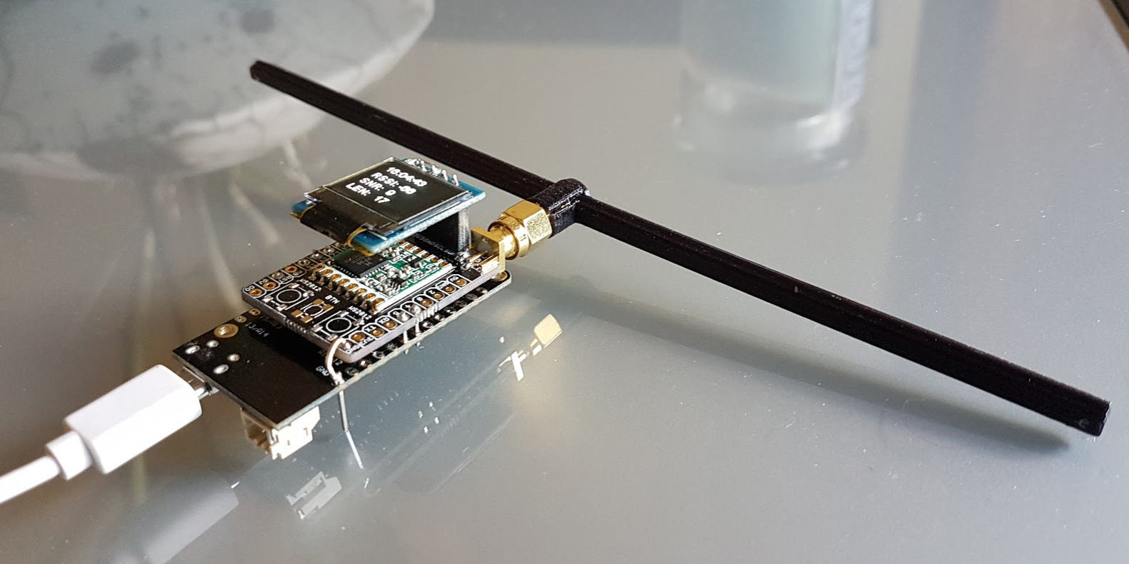
Add a nice dipole antenna

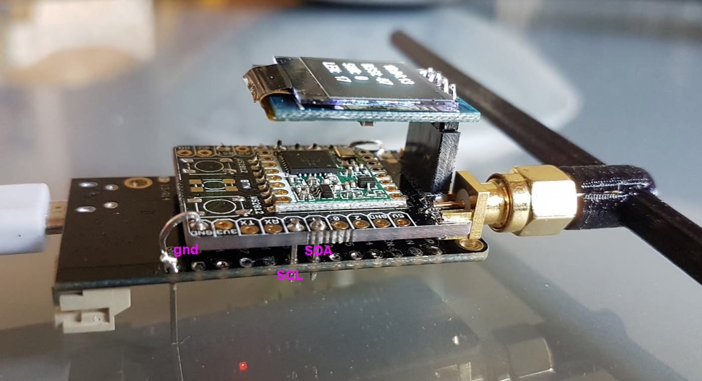
Stack all this together and you get your tiny compact ESP32 gateway :slight_smile:
ESP32gateway

As you can see, the Hallard’s shield and the Lolin32 lite do have the same pin spacing. And, as you can mux pretty much all the pins on the ESP32, it’s easy to adapt the software.
Only the +3.3V and the Gnd need a separate pin, but both of them are very close !

LeftSide

RightSide

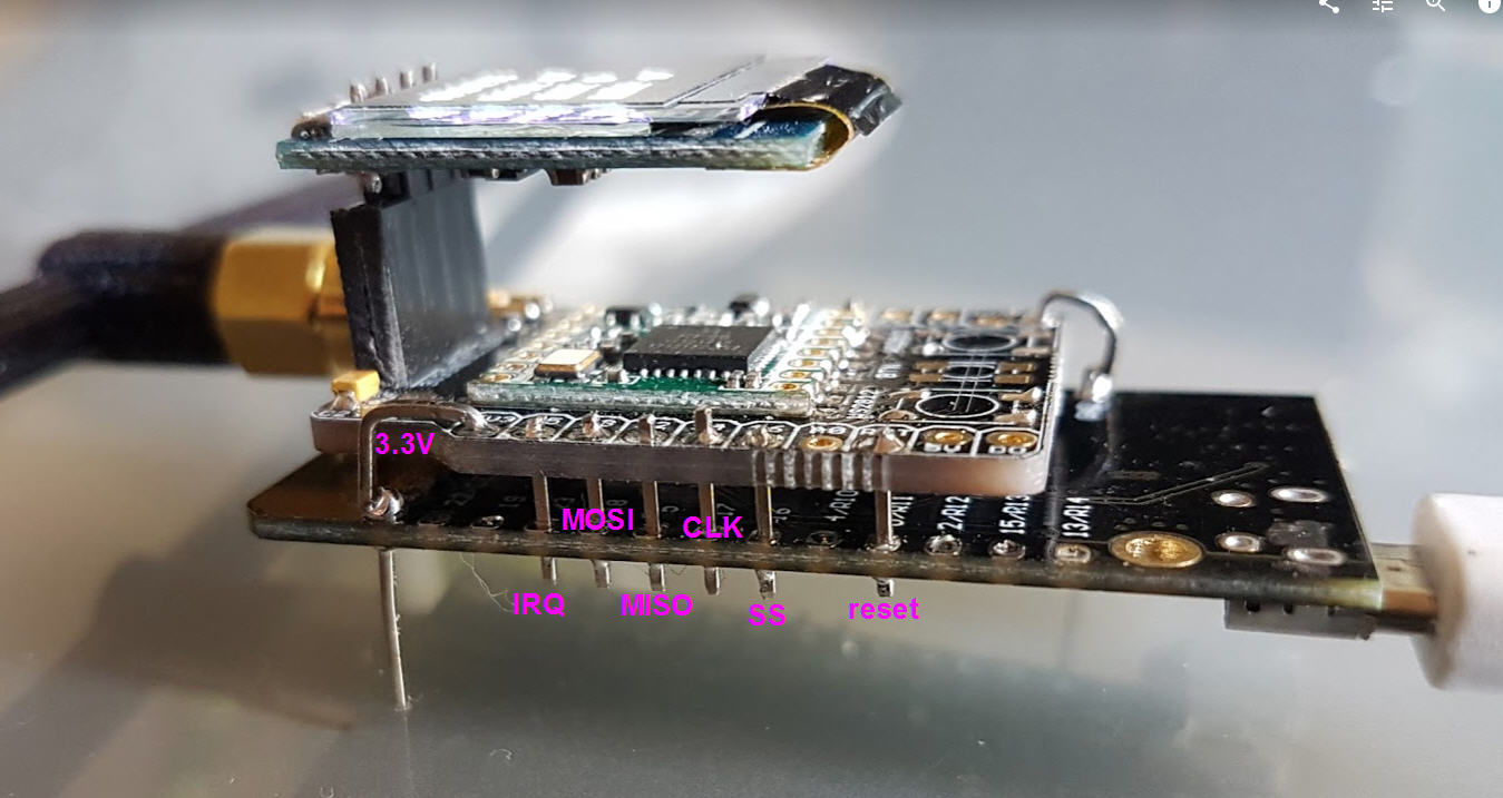
Pin Mapping is done as follow:

// if OLED Display is connected to i2c
// OLED 2 requires this updated library that is resolution independent https://github.com/DaveRichmond/esp8266-oled-ssd1306
#define OLED 1 // Make define 1 or 2 on line if you have an OLED display connected 1=128x64 2=64*48
#if OLED>0
#define OLED_SCL 25 // GPIO5 / D1
#define OLED_SDA 33 // GPIO4 / D2
#endif

and

// Use your own pin definitions, and uncomment #error line below

struct pins {
uint8_t dio0=23; // GPIO5 / D1. Dio0 used for one frequency and one SF
uint8_t dio1=23; // GPIO4 / D2. Used for CAD, may or not be shared with DIO0
uint8_t dio2=23; // GPIO0 / D3. Used for frequency hopping, don’t care
uint8_t ss=16; // GPIO15 / D8. Select pin connected to GPIO15
uint8_t rst=0; // GPIO0 / D3. Reset pin not used
// Pin definetion of WIFI LoRa 32
// HelTec AutoMation 2017 support@heltec.cn
#define SCK 17 // GPIO5 – SX127x’s SCK
#define MISO 5 // GPIO19 – SX127x’s MISO
#define MOSI 18 // GPIO27 – SX127x’s MOSI
#define SS 16 // GPIO18 – SX127x’s CS
#define RST 0 // GPIO14 – SX127x’s RESET
#define DI00 23 // GPIO26 – SX127x’s IRQ(Interrupt Request)
} pins;
//#error “Pin Definitions _PIN_OUT must be 1(HALLARD) or 2 (COMRESULT)”
#endif

I have tested it with:
Loragateway V5
Lmic as a lorawan node
lora library as sender or receiver

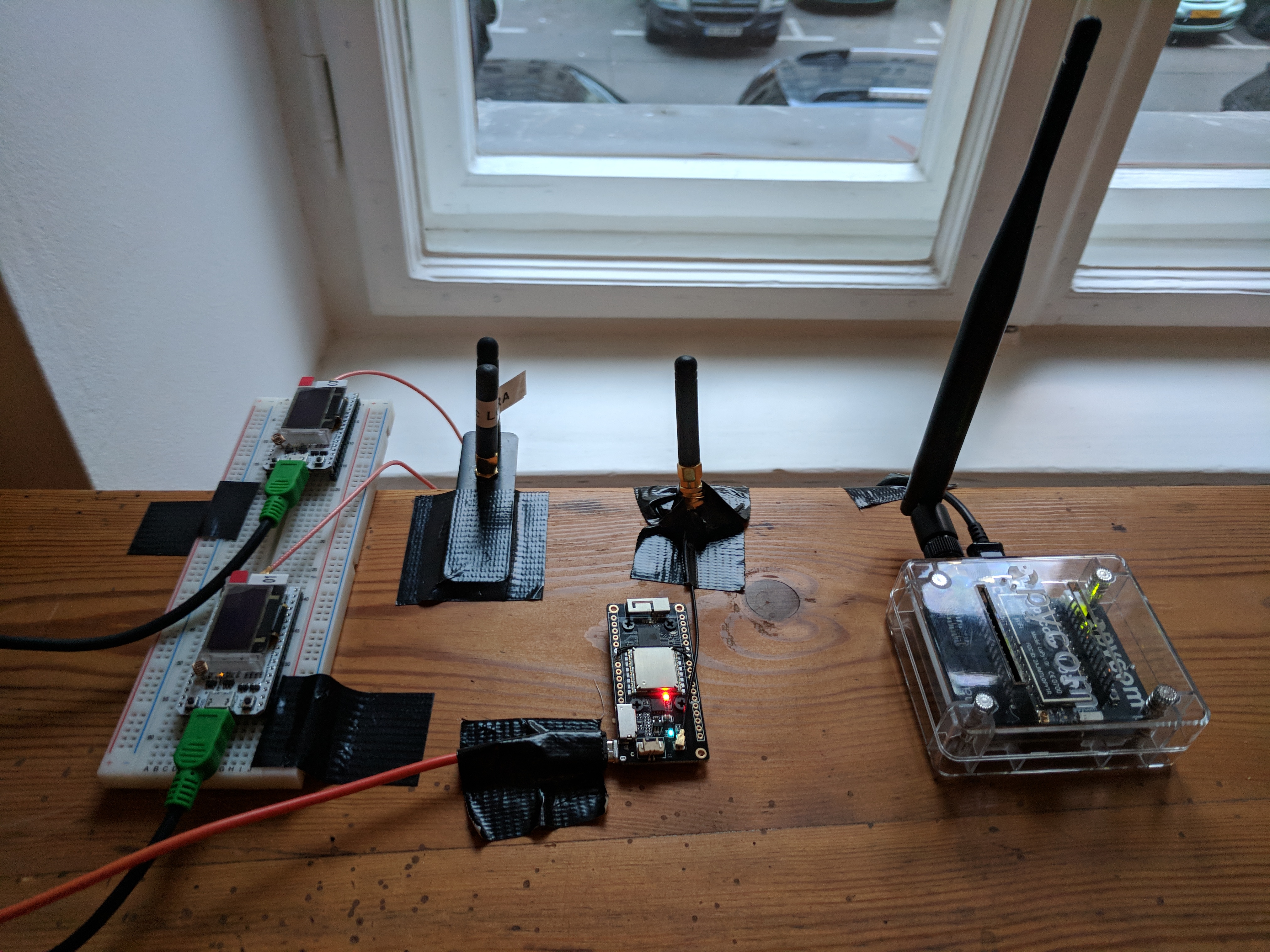
Range as been measured to more than 8.7km with this antenna, SF11 and BW 125

Quite happy with this result :star_struck:
JP

9 Likes

Thanks for sharing.

for optimal result… do you mount that antenna horizontal (like on the picture) or vertical ?

I was busy to run the Heltec board in deep sleep mode. What I observed is that SX1276 receives RST signal. Either by power down or by wake up and initialization.

  1. The board pictures - https://github.com/mirtcho/HelTec_ESP32_LoRa/wiki
  2. The Arduino sketch - https://github.com/mirtcho/HelTec_ESP32_LoRa/tree/master/LoRaReceiver868_sleep
    a. Sketch highliths
    i. Sketch LoRaReceiver868_sleep is based on LoRareceiver868 sketch which works fine - https://github.com/mirtcho/HelTec_ESP32_LoRa
    ii. At first startup – performs board setup + SX1276 initialization
    iii. Initialize wakeup from timer
    iv. Go to deep sleep
    v. Wake up – board minimal initialization
    vi. Reading SX1276_REG_VERSION = 0x12
    vii. Reading of SX1276_REG_OP_MODE = 0x9 – I expect something like 0x81 –Loramode_bit+RxContinuesMode. 0x9 is the reset value.
    My conclusion is that reset pin was went High in the time between deep_sleep command and next Lora::ParsePacket()

I have described the issue in details here - https://github.com/mirtcho/HelTec_ESP32_LoRa/issues/1

Does somebody experienced similar problem?
Is there some kind of pinmux/GPIO initialization file for ESP32?
Thanks in advance

Does anyone know how much power one can draw from a digitalpin of the TTGO V2 or heltec boards?

I need to be able to control when I power up or down some sensors, but don’t know how much I can load on digital pins.

Thanks for your help!