Just giving a shout out for @nicbkw
Nice article!
https://www.thethingsnetwork.org/labs/story/heltec-lorawan-gps-quick-start
I’m thinking it would be nice to have another version of the code - which outputs the data to Cayenne and reports back RSSI to the OLED!
Before I have a go, has anyone done that?
2 Likes
One point regarding the OLED-display and multitasking with LMiC:
U8X8_SSD1306_128X64_NONAME_SW_I2C
This driver emulates I2C interface by software on GPIO pins. But on the Heltec the OLED-display is wired to pins, where the Heltec can do I2C by hardware. This keeps the CPU from load shifting bits on the wires. So better use:
U8X8_SSD1306_128X64_NONAME_HW_I2C
Regarding multitasking i found out that it is possible to let LMiC run on core 0 of ESP32 while application code (e.g. polling the GPS) can be run parellel on core 1. Of course you need to take care of possible race conditions in this setup.
3 Likes
Hi @bluejedi,
With regards to the “exact same setting as described in the topic start” I understand you refer to the pin mappings? lmic_pinmap lmic_pins I can find in the Sketch, but I’m lost with SPI.begin. Also, the inlcude for SPI.h shows SPI in red. Would that indicate there are multiple SPI.h found by Arduino Sketch?
Update: I’ve used the pin numbers as mentioned and get a failure on lmic\radio.c line 689 (if that is the actual source line then it says: " ASSERT(v == 0x12 );" for “#ifdef CFG_sx1276_radio”):
Starting
FAILURE
C:\Users\Jean-Pierre\Documents\Arduino\libraries\arduino-lmic-master\src\lmic\radio.c:689
-
This failure shows that either your pin mapping is wrong and/or selected chip type (1272 vs.1276) does not match.
-
You should not open the SPI interface in your code, since this done by LMiC.
-
If your board hardware uses non arduino style wiring of the SPI interface (MOSI, MISO, SCK) you need to patch the original LMiC code, or use the patched LMiC repo from jpmeijers, which enhances the lmic_pin_type struct.
As @Verkehrsrot says, no need to open SPI with SPI.begin yourself.
I was doing it myself (but did not give any errors).
I apparently copied the SPI initialization with other lines of code (from another sketch).
I will remove the SPI line from the topic start (and do some other edits for TTGO V2 soon).
Are you using the Heltec Lora Wifi 32 board definition?
(If you dont see it then update the Arduino stack for ESP32 first.)
So for ESP32 it is ok to use ‘Hardware I2C’ also when non-standard I2C pins are used (due to the remapping feature of ESP32)?
.
Heltec and TTGO V1 use non-standard I2C pins for the OLED display (different from what is defined for I2C in the board in the Arduino definitions). TTGO V2 uses the standard I2C pins 21 and 22.
When using 'Heltec Wifi LoRa 32' as board type (for both Heltec and TTGO as there currently do not seem to be board definitions for TTGO yet):
- for Heltec and TTGO V1: SCL and SDA pin numbers for the display must be specified because they are not the default I2C pins.
- for TTGO V2: SCL and SDA pin numbers for the display do NOT have to be specified for the U8g2/U8x8 constructor because it uses the standard I2C pins (as defined in the Heltec board definition).
U8x8 constructor signature:
U8X8_SSD1306_128X64_NONAME_HW_I2C(uint8_t reset = U8X8_PIN_NONE, uint8_t clock = U8X8_PIN_NONE, uint8_t data = U8X8_PIN_NONE)
So, for Heltec and TTGO V1 use:
U8X8_SSD1306_128X64_NONAME_HW_I2C display(/*rst*/ 16, /*scl*/ 15, /*sda*/ 4);
For TTGO V2 use:
U8X8_SSD1306_128X64_NONAME_HW_I2C display(/*rst*/ U8X8_PIN_NONE);
Yes, Heltec board uses pin remapping feature on I2C interface. This makes it possible to use the I2C hardware driver to free the CPU from low level bit shifting in the wires. So, you are right, pin mapping is to be explicitly specified in the U8x8 constructor. Sorry, i forgot that.
I had success with this settings for an Heltec “Lora-32” board:
// Hardware pin definitions for Heltec LoRa-32 Board with OLED SSD1306 I2C Display
#define OLED_RST 16 // ESP32 GPIO16 (Pin16) -- SD1306 Reset
#define OLED_SDA 4  // ESP32 GPIO4 (Pin4)   -- SD1306 Data
#define OLED_SCL 15 // ESP32 GPIO15 (Pin15) -- SD1306 Clock

#include <U8x8lib.h>

U8X8_SSD1306_128X64_NONAME_HW_I2C u8x8(OLED_RST, OLED_SCL, OLED_SDA);
In original code from Heltec (Aaron Lee) there is a reset procedure when initializing the display:
// Display init Hi-Lo-Hi on Display reset pin
pinMode(OLED_RST,OUTPUT);
digitalWrite(OLED_RST, LOW);  // set GPIO16 low to reset OLED
delay(50); // 5ms
digitalWrite(OLED_RST, HIGH); // while OLED is running, must set GPIO16 in high
When using the u8g2 / u8x8 library this reset procedure is done by the library, so you don’t need to code this.
I tried to do so, but for an unknown reason, sending the lpp data with LMIC failed in my sketch, so if you have anything for me to compare with, it would be nice 
In the meantime, I modified a sketch to deep sleep between sendings.
Deep sleeping make it more power savvy than RAK811 trackerboard (that I don’t know how to optimise it, with GPS disabled), or seeeduino LoRaWAN (same thing, as I don’t have external trigger for wakeup but only a timer)
I just saw your answer @arjanvanb and will give a try to your hints in the next few days.
Once the board joined using OTAA, if I make the keys persistant and switch to ABP after joining, may I keep them “forever” in EEPROM or would I need to rejoin at some point (so keeping in RTC memory that will be flushed when battery is empty is better)?
Thanks a lot for your help making things clearer for me!
My bad:
Should read:
U8X8_SSD1306_128X64_NONAME_HW_I2C display(/*rst*/ 16, /*scl*/ 15, /*sda*/ 4);
Please prevent repeating information that was already posted in the thread because it bloats the thread and makes information more difficult to find (e.g. Heltec pin numbers are already described in topic start).
I have extended the pin mappings section in the topic start and added exceptions for the TTGO V2 board. Hope this makes it more clear.
https://www.thethingsnetwork.org/docs/devices/arduino/api/cayennelpp.html
Have you looked at the standard "Basic_library_TTN" sketch?
Surely, all you need is something like this?
(Obviously, replace the values with your variables)
#include <CayenneLPP.h>
CayenneLPP lpp(51);
lpp.reset();
lpp.addTemperature(1, 22.5);
lpp.addBarometricPressure(2, 1073.21);
lpp.addGPS(3, 52.37365, 4.88650, 2);
And the LMIC version of this
ttn.sendBytes(lpp.getBuffer(), lpp.getSize());
Also, don’t forget to change the payload function to “Cayenne”
N.B. I’ve put some example code for the Heltec (V1) in post 123 here
But this would be better perhaps?
https://www.thethingsnetwork.org/labs/story/heltec-lorawan-gps-quick-start
Also, this was created about the Heltec
1 Like
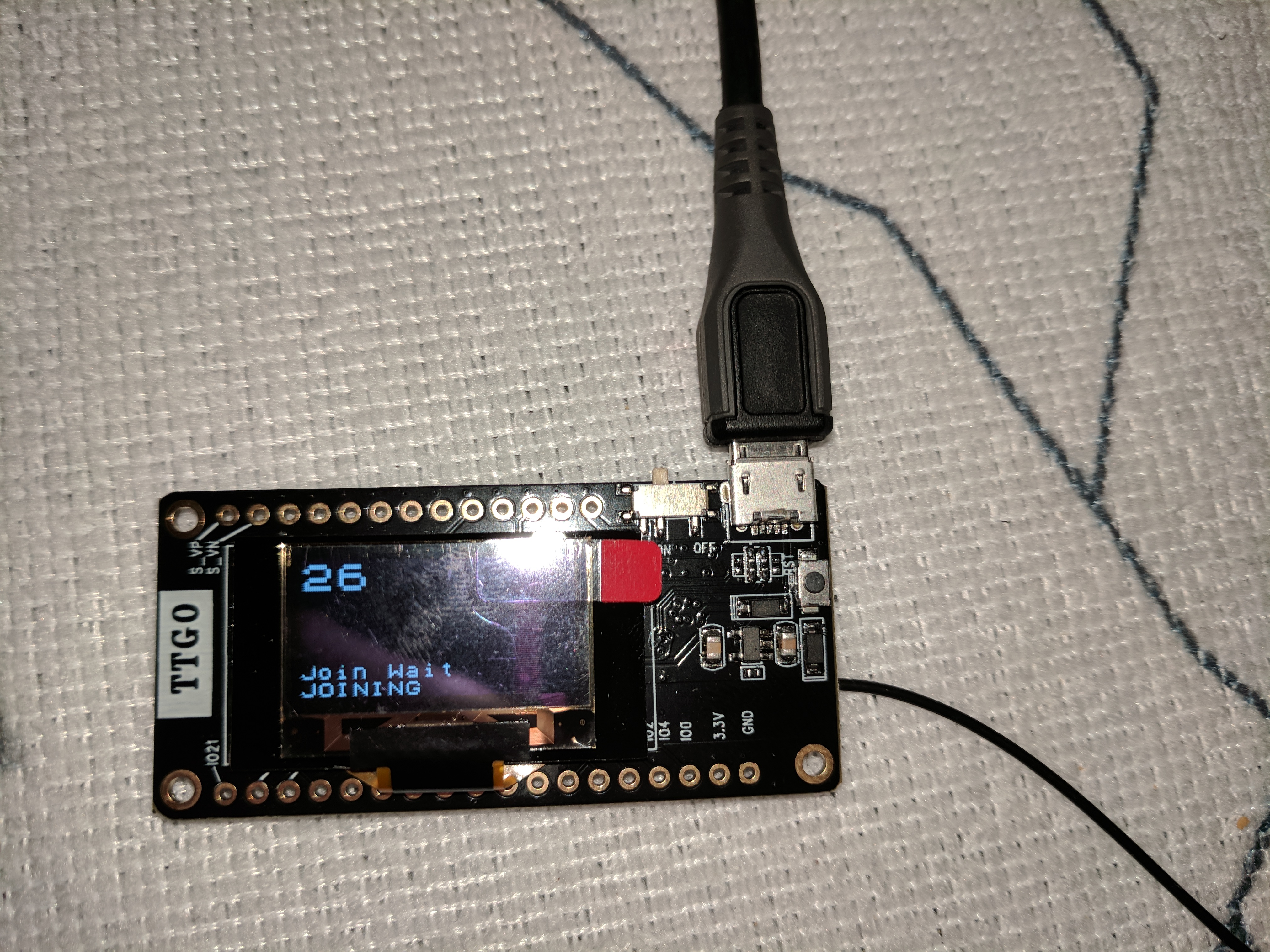
My first TTGO v2 arrived today from Ali / Lilygo.
PCB quality looks better than that one seen with crooked parts.
I already put my test code on it, taylored the pinout, wired DIO1 and DIO2 to GIO33+32 on back side of pcb, and set lmic to SX1276 radio.
But no join yet. Even no packets to see on the gateway. Looks like there is no or near-to-nothing RF output. But need to double check what’s going wrong.
PS: the display is clear white, only on the picture it looks blue.
You could try LMIC-Arduino ttn-abp.ino first to rule out other factors and not depend on downlink messages. ABP will start sending immediately.
I got TTGO LoRa board too and tried to use Platformio+atom with it. Platformio does not provide the exact project name for this board. Does this work if I choose Heltec wifi Lora? I did not success to upload hex. The screen will blink several times and cannot upload. What is on my screen are as following.
Uploading .pioenvs\heltec_wifi_lora_32\firmware.bin
esptool.py v2.1
Connecting…………………………
A fatal error occurred: Failed to connect to ESP32: Timed out waiting for packet header
*** [upload] Error 2
[ERROR] Took 61.27 seconds
Somsak
If you use heltec board definitions, you need to adjust pin some pin mappings, see first posts in this topic.
If you upload hex with platformio make sure that the serial port is not busy, e.g. because you have an open serial monitor window.
The TTGOv2 should be boot flashable without any preparations, just plug in USB and go.
1 Like
Here’s my LMiC log after starting the module and trying to join, but not join.
Can anyone see what’s going wrong here? Is the module is TX’ing?
I don’t see a join request packet on my gateway.
RXMODE_RSSI
552236: engineUpdate, opmode=0x8
552267: Scheduled job 0x3ffc8f94, cb 0x400f9314 ASAP
[I][lorawan.cpp:89] do_send(): Packet queued
558469: Running job 0x3ffc8f94, cb 0x400f9314, deadline 0
[I][lorawan.cpp:134] onEvent(): EV_JOINING
559182: engineUpdate, opmode=0xc
559194: Uplink join pending
559197: Airtime available at 741420 (previously determined)
559260: Uplink delayed until 741420
559461: Scheduled job 0x3ffc8f94, cb 0x400f9624 at 741295
741606: Running job 0x3ffc8f94, cb 0x400f9624, deadline 741295
741614: engineUpdate, opmode=0xc
741617: Uplink join pending
741619: Airtime available at 741420 (previously determined)
741936: Ready for uplink
742107: Updating info for TX at 741617, airtime will be 3856. Setting available time for band 0 to 4597617
742693: TXMODE, freq=868100000, len=23, SF=7, BW=125, CR=4/5, IH=0
746732: irq: dio: 0x0 flags: 0x8
746742: Scheduled job 0x3ffc8f94, cb 0x400f8b5c ASAP
747356: Running job 0x3ffc8f94, cb 0x400f8b5c, deadline 0
747363: Scheduled job 0x3ffc8f94, cb 0x400f8984 at 1056097
1056106: Running job 0x3ffc8f94, cb 0x400f8984, deadline 1056097
1056223: RXMODE_SINGLE, freq=868100000, SF=7, BW=125, CR=4/5, IH=0
1063106: irq: dio: 0x1 flags: 0x80
1063115: Scheduled job 0x3ffc8f94, cb 0x400f95d8 ASAP
1063731: Running job 0x3ffc8f94, cb 0x400f95d8, deadline 0
1063736: Scheduled job 0x3ffc8f94, cb 0x400f89d8 at 1121605
1121856: Running job 0x3ffc8f94, cb 0x400f89d8, deadline 1121605
1121877: RXMODE_SINGLE, freq=869525000, SF=12, BW=125, CR=4/5, IH=0
1138731: irq: dio: 0x1 flags: 0x80
1138740: Scheduled job 0x3ffc8f94, cb 0x400f9600 ASAP
1139356: Running job 0x3ffc8f94, cb 0x400f9600, deadline 0
1139363: Scheduling next join at 4988930
1139367: Scheduled job 0x3ffc8f94, cb 0x400f9624 at 1139367
1140169: Running job 0x3ffc8f94, cb 0x400f9624, deadline 1139367
1140173: engineUpdate, opmode=0xc
1140176: Uplink join pending
1140267: Airtime available at 4988930 (previously determined)
1140609: Uplink delayed until 4988930
1140821: Scheduled job 0x3ffc8f94, cb 0x400f9624 at 4988805Some posts up I suggested to test with ABP first. That is still what I would like to suggest. Less complicated, no joining dependencies/difficulties. It just sends uplink messages from the start, whether any gateway is listening or responding or not. That will be easier to troubleshoot.
Btw, how did you get that detailed output, is there a parameter to configure the detail of logging?
I will try ABP test, too. But since i don’t see a join request packet on the gateway, and the lmic log seems to say that there is no failure in the software stack, i’m expecting that ABP won’t work either. But let’s see.
Lmic logging is possible by setting
#define LMIC_DEBUG_LEVEL 2
in lmic/config.h
2 Likes
Correct, but better to start with the bare basics to simplify troubleshooting.
1 Like
I received a Heltec WiFi LoRa board last week and have since then tried to connect to it. The basic problem is that the serial connection doesn’t seem to work. If I try to upload any code it looks like this:
Archiving built core (caching) in: C:\Users\osbex\AppData\Local\Temp\arduino_cache_782066\core\core_esp8266_esp8266_nodemcu_CpuFrequency_80,UploadSpeed_9600,FlashSize_4M3M_01696216298cb0bf10a7299dfddad9bf.a
Sketch uses 226729 bytes (21%) of program storage space. Maximum is 1044464 bytes.
Global variables use 31936 bytes (38%) of dynamic memory, leaving 49984 bytes for local variables. Maximum is 81920 bytes.
Uploading 230880 bytes from C:\Users\osbex\AppData\Local\Temp\arduino_build_480452/WiFiScan.ino.bin to flash at 0x00000000
warning: espcomm_send_command: didn't receive command response
warning: espcomm_send_command(FLASH_DOWNLOAD_BEGIN) failed
error: espcomm_upload_mem failed
error: espcomm_upload_mem failed
Have tried everything, for example changing cables, computers, baud rates, tried to set PINs on the board, googled every forum/github/ali page etc. Noone seems to have the same issue. There are other HW issues, typically related to antennas, but nothing about getting connected to the actual board.
Does anyone have a suggestion on something I could try before I order a TTGO board instead?