Big ESP32 + SX127x topic part 3

Heltec devices are now available in the LoRaWAN Device Repository

Heltec has added their LoRa devices to the LoRaWAN Device Repository.

This means that these devices can now be selected from the device list when adding a new device in the V3 Console.

2 Likes

The latest version of Arduino Core ESP32 now has additional boards added. Finally also additions for TTGO LoRa32 V2.x.x boards:

  • ttgo-lora32-v2
  • ttgo-lora32-v21new

For Heltec boards the Wireless Stick and Wireless Stick Lite were added already earlier:

  • heltec_wireless_stick
  • heltec_wireless_stick_lite

As usual, don’t blindly trust board definitions in the Arduino cores:

I noticed an error in the ttgo-lora32-v21new BSP:

#define LORA_RST 12 // GPIO14 - SX1276 RST

But uh, oh, LoRa reset for this board is connected to GPIO23
(Well, at least according to LilyGO’s pinout diagram for this board.)

And similar error in the ttgo-lora32-v2 BSP:

#define LORA_RST 12 // GPIO14 - SX1276 RST

The same ‘12 commented as 14’. However, in reality LoRa reset on the
v2.0 board board is NOT connected to any GPIO but to EN/RST of the ESP32…

I wonder what people are creating these board definitions.
How hard can it be to check consistency between code, comments and reality and correct any errors before this stuff gets released globally to thousands of users?

The topic-start has been updated with the LMIC-node example and a link to the pinout-diagrams repository which contains pinout diagrams for most of the boards described in this topic. In addition some notes were added for The Things Stack V3.

2 Likes

Hey guys, great thread here!

sadly im trying to connect my TTGO Lora32 v1.0 to TTN, without success so far. I hoped i would get the new example from the LMIC-node to work but this is without success so far. A single channel gateway i am running here is receiving something that doesnt look completely wrong. I know the TTGO Lora32 isnt listed in the supported devices. Since the lmic pins are the same as on the Heltec Lora32 V1 i gave it a try. I suppose some configuration is still wrong since packets are received by the gateway but not correctly forwarded to the network?!

I use ABP from LMIC-node example since i am using a single channel gateway in my flat. With OTAA i got no succcess either. There should be some Gateways not too far away, but for testing purposes i decided to go with ABP and an own 1-Ch-Gateway.

This is the received packet as shown in the gateway console:

Maybe someone of you can see waht im doing wrong. thanks a lot in advance

{
  "name": "gs.up.receive",
  "time": "2021-10-16T09:34:08.455140041Z",
  "identifiers": [
    {
      "gateway_ids": {
        "gateway_id": "b8f009ffffcca210"
      }
    },
    {
      "gateway_ids": {
        "gateway_id": "b8f009ffffcca210",
        "eui": "B8F009FFFFCCA210"
      }
    }
  ],
  "data": {
    "@type": "type.googleapis.com/ttn.lorawan.v3.UplinkMessage",
    "raw_payload": "QOFECyaAAwAKVIab8UMu",
    "payload": {
      "m_hdr": {
        "m_type": "UNCONFIRMED_UP"
      },
      "mic": "m/FDLg==",
      "mac_payload": {
        "f_hdr": {
          "dev_addr": "260B44E1",
          "f_ctrl": {
            "adr": true
          },
          "f_cnt": 3
        },
        "f_port": 10,
        "frm_payload": "VIY="
      }
    },
    "settings": {
      "data_rate": {
        "lora": {
          "bandwidth": 125000,
          "spreading_factor": 7
        }
      },
      "coding_rate": "4/5",
      "frequency": "868099975",
      "timestamp": 161729712
    },
    "rx_metadata": [
      {
        "gateway_ids": {
          "gateway_id": "b8f009ffffcca210",
          "eui": "B8F009FFFFCCA210"
        },
        "timestamp": 161729712,
        "rssi": -113,
        "channel_rssi": -113,
        "snr": 2,
        "uplink_token": "Ch4KHAoQYjhmMDA5ZmZmZmNjYTIxMBIIuPAJ///MohAQsJmPTRoMCJC5qosGEMKK/dgBIICf3r7aBA=="
      }
    ],
    "received_at": "2021-10-16T09:34:08.455034178Z",
    "correlation_ids": [
      "gs:conn:01FJ472WX5SW5A0DHHMFAXWKYC",
      "gs:uplink:01FJ477527VN20ZQ7PJ0C9AWQC"
    ]
  },
  "correlation_ids": [
    "gs:conn:01FJ472WX5SW5A0DHHMFAXWKYC",
    "gs:uplink:01FJ477527VN20ZQ7PJ0C9AWQC"
  ],
  "origin": "ip-10-100-12-248.eu-west-1.compute.internal",
  "context": {
    "tenant-id": "CgN0dG4="
  },
  "visibility": {
    "rights": [
      "RIGHT_GATEWAY_TRAFFIC_READ",
      "RIGHT_GATEWAY_TRAFFIC_READ"
    ]
  },
  "unique_id": "01FJ4775275M22MKG96D7MXAYY"
}
We do not support Single or Dual Packet Forwarders. Please disconnect it from TTN and get a LoRaWAN gateway NOT a LoRa ‘Gateway’ - one that fully supports 8 channels, across the full spread of SF’s or more. These are disruptive to other users on the network (use Forum search) and cause issues of the type you may be experiencing yourself. Come back when in range of a LoRaWAN gateway or get one for your own use and add to the communities coverage then many here will be able to assist you.

It may be that if the other gateways are really in coverage range then simply scrapping your SCPF will allow them to correctly start servicing your node…

Thanks a lot for the fast reply. SCPF is shut off now.

There should be a few gateways not too far away, but im not sure if the TTGO Lora32 V1.0 has enough range. Ill try to let it run for a while. Should i then try to go with OTAA since this is the preferred way then? Just went with ABP since i’ve read OTAA isnt possible with the SCPF i was using

Thank for this very useful comparison.
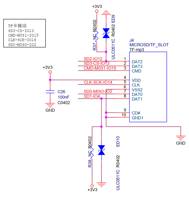
Has anybody worked out which peripheral is connected to which bus for the TTGO LoRa V2.1.6? In these pin-out diagrams it would appear that the SD card is connected using its native iterface (CMD, SD0, etc.) but in another pinout for the same board, pinout-diagrams/TTGO LoRa32 V2.1.6 Pinout.pdf at main · lnlp/pinout-diagrams · GitHub, the SD card appears to be connected to a SPI bus. From the choice of pins, it looks like it maybe H-SPI. Which is the definitive diagram?
The SX12xx appears to be connected to V-SPI. Is this the case does anybody know?
I am working on a project that will connect to the board via SPI with fairly tight latency requirements; so I do not want to share the SPI bus with the LoRa activity. Sharing the bus with the SD card (if it actually uses a SPI would be OK as I have control when this would be active.
Any advice would be greatly appreciated.

It looks like the SD card may be wired so that it can be used in 1 bit MMC mode or SPI mode, in my experience, MMC mode is more reliable.

With TTN use, there will not be a great deal of LoRa based SPI activity, so there may not be an issue. However nodes that have ‘tight’ connection latencies might not be a good fit for TTN.

Where is the first pinout diagram?

Which one of both diagrams is correct?
Try to find a corresponding schematic diagram of the board to verify it.
The problem with TTGO boards documentation is that it is often not (fully) reliable, can contain errors and omissions, different versions may exist and not clear which one is (more) correct because document versioning is lacking.

That can be checked by looking up the GPIO numbers for V-SPI in the ESP32 datasheet.

Thank you LoRa Tracker for your prompt and astute reply. I am sure you are correct; the SD card slot is wired for both approaches. This belief is reinforced by the fact that the GPIO pins used are the default used by Espressif’s SD Card driver (SDMMC Host Driver - ESP32 - — ESP-IDF Programming Guide v4.4 documentation). However, I suspect that some other examples for the Arduino IDF use one of the SPI drivers. These are all brought out on the pins of the TTGO LoRa board. A warning to anyone trying to run more than one device off the same bus. If the devices are controlled from difference tasks, you have to be very sure they will not clash. The Espressif SPI driver is not thread safe and I would be surprised if the Arduino driver was.

The GPIO pin numbers connected to the SX12xx hint at the VSPI (aka SPI3) but this example (esp-idf-sx127x/lora.c at main · nopnop2002/esp-idf-sx127x · GitHub) actually maps these to HSPI (aka SPI2). Which goes to show that pin numbers are only a hint at best!

I plan to identify 4 GPIO pins that are not being used for anything else and map these to which ever SPI interface not being used by the LoRa driver.

Many thanks again.

Well you can re-map the pins and it does work.

However, which LoRa driver are you using ?

The first diagram with the SD card mapped to its native interface was posted by yourself, bluejedi, “TTGO LoRa32 V2.1 rev1.6 versus TTGO LoRa32 V2.0 pin layouts”, back in October 2019. And very useful it is too. It corrects TTGO’s mistake in mapping IO0 and IO4 to power and ground for starters! Thanks.

Good catch.

The TTGO LoRa32 V2.1.6 pinout has now been corrected, enhanced and the file has been renamed.

Maybe this helps:

Below microSD connection details come from the TTGO LoRa32 V2.1.6 schematic diagram:

TTGO V2.1.6 microSD schematic diagram

A post was split to a new topic: Programming ESP32 + SX1276 in Rust

Hello,

I have an issue with my TTGO SD LoRa 32 V2.0
I would like to use SD card and LMIC in the same sketch, but theese 2 libraries do not work together in my sketch.
Are there some samples using SD card and LoRaWAN together ?

NB :

  • Sketch using SD card alone works
  • Shetch using LMIC alone works well with TTN

I have not used LMIC on the ESP32, but in what way does the SD card and LoRa device ‘not work together’ ?

IIRC some modules in the market can ‘share’ pinouts & functions e.g. GPIO, SPI bus(es) etc. Is this one where say a SD Card connection conflicts with the LoRa radio function? :thinking: perhaps SPI i/f?

Update, just scrolled up and saw discussion earlier this year on just such connections - perhaps @bluejedi can advise…

Step away from the soldering iron …

SPI can share the In, Out & Clock but each item connected needs it’s own Select. Arduino broke it all by assuming only one SPI device when they made pin 10 as Select. So almost all libraries use that assumption. Sometimes you can override the SS / NSS / CS pin in the library - you can in LMIC but the Select will be hardwired on the PCB. Whereas the Select for the SD Card can be moved to a different pin which would then need specifying in the code - either when initialised or by hacking the library, depending on what library you are using.

The general advice (I don’t have a source) is to not share the SPI bus where the LoRa radio is connected to with other peripherals, when using (Arduino) LMIC. This is because LMIC uses its own proprietary scheduler and timing and was not designed with sharing the SPI bus in mind.

Fortunately the ESP32 supports two different SPI busses. To use the second SPI bus you will have to create a second SPI object instance and map specific ESP32 pins for the second SPI.
In addition you will need to use libraries that can handle more than only the standard default SPI instance (allow you to specify a specific SPI object instance for your SDCard).

Above is a description for the approach, but you will have to search for the nitty gritty details for how to exactly do this in code yourself (I don’t have examples at hand).

For SD cards there afe different interfaces / modes you can use: One-bit SD mode, four-bit SD mode or SPI. Check the ESP32 documentation/datasheet for which interface requires/allows which IO ports.

Be aware that it depends on the type of ESP32 board which GPIO ports are (not) available as physical pins on the board. It is also possible that some board type already uses some of the required GPIO’s for other purposes.
Some boards are better (or worse) designed in this aspect than others so your mileage may vary.