Unless you provide any concrete details it will be very difficult for others to provide you with actual help.
1 Like
I have used this library successfully with the TTGo V2
cheers
Paul
1 Like
- Concurrent (not mutexed) access by two (or more) RTOS tasks to i2c bus
Thanks Verkehrsrot,
I cloned the paxcounter (https://github.com/cyberman54/ESP32-Paxcounter) and set ii up as described in the readme. The lora start and is switching from JOINING to JOIN WAIT. Left the board in this state for several hours and also tried to drive around in the car in zones which according to ttnmapper should be covered, but the paxcounter keeps on JOIN WAIT. Is there any additional cabling needed for TTGO T3 2.1 1.6? Something else I can check?
Thanks again
Please try again with current version 1.9.x from development branch, and report here if you see a difference in joining behaviour.
No additional cabling needed for that board.
I switched to the development branch- but I do not understand what you mean by version 1.9.x? Do I have to specify a version?
With the development branch I do get following logs:
[W][lorawan.cpp:462] lora_enqueuedata(): LORA sendqueue is full
[I][senddata.cpp:73] sendCounter(): Counter cleared
[W][lorawan.cpp:462] lora_enqueuedata(): LORA sendqueue is full
[I][cyclic.cpp:57] doHousekeeping(): Voltage: 4878mV
[I][lorawan.cpp:340] onEvent(): JOIN WAIT
[I][cyclic.cpp:57] doHousekeeping(): Voltage: 4862mV
[W][lorawan.cpp:462] lora_enqueuedata(): LORA sendqueue is full
[I][senddata.cpp:73] sendCounter(): Counter cleared
[W][lorawan.cpp:462] lora_enqueuedata(): LORA sendqueue is full
[I][cyclic.cpp:57] doHousekeeping(): Voltage: 4564mV
[I][cyclic.cpp:57] doHousekeeping(): Voltage: 4660mV
[W][lorawan.cpp:462] lora_enqueuedata(): LORA sendqueue is full
[I][senddata.cpp:73] sendCounter(): Counter cleared
[W][lorawan.cpp:462] lora_enqueuedata(): LORA sendqueue is full
[I][cyclic.cpp:57] doHousekeeping(): Voltage: 4750mV
[I][cyclic.cpp:57] doHousekeeping(): Voltage: 4244mV
[W][lorawan.cpp:462] lora_enqueuedata(): LORA sendqueue is full
[I][senddata.cpp:73] sendCounter(): Counter cleared
[W][lorawan.cpp:462] lora_enqueuedata(): LORA sendqueue is full
It is the same as with the master branch
You’re getting no join. Check your TTN coverage.
Thanks Verkehrsrot.
Indeed it has been a problem of coverage. I drove next to the next free gateway and there it started. I think this gateway is not set up proberly, as I worked only up to a distance of approx. 20m from this gateway.
1 Like
Hi bluejedi,
Sorry for the late reply, I found a solution, but before that, I will answer your questions:
-
The board that I select in the Arduino IDE is “Heltec Wifi LoRa32”
-
The first library I used was Adafruit, then I switched to Sparkfun and then
returned to Adafruit. -
I initialized the library with bme.begin ().
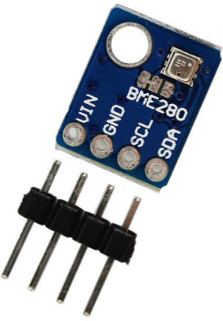
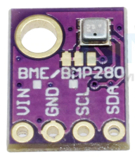
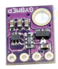
In any case I found out that the problem is due to a two different types of BME280 sensors smaller than usual, take a look here and here. While with this type no problem, everything works fine even with the Adafruit library. It remains to understand why all the sensors of the aforementioned type don’t work properly. I tried a dozen of them all working perfectly with other projects.
Thank you for the support you are giving me @Sandgroper @bluejedi @Paul_Stewart !
1 Like
The smaller ones are special 5.0V versions and have a 3.3V voltage regulator.
When using these with 3.3V it may be possible that supply voltage gets too low which could explain the problems. I suspect that the chip on the left is a level converter which may also cause issues when used with 3.3V.
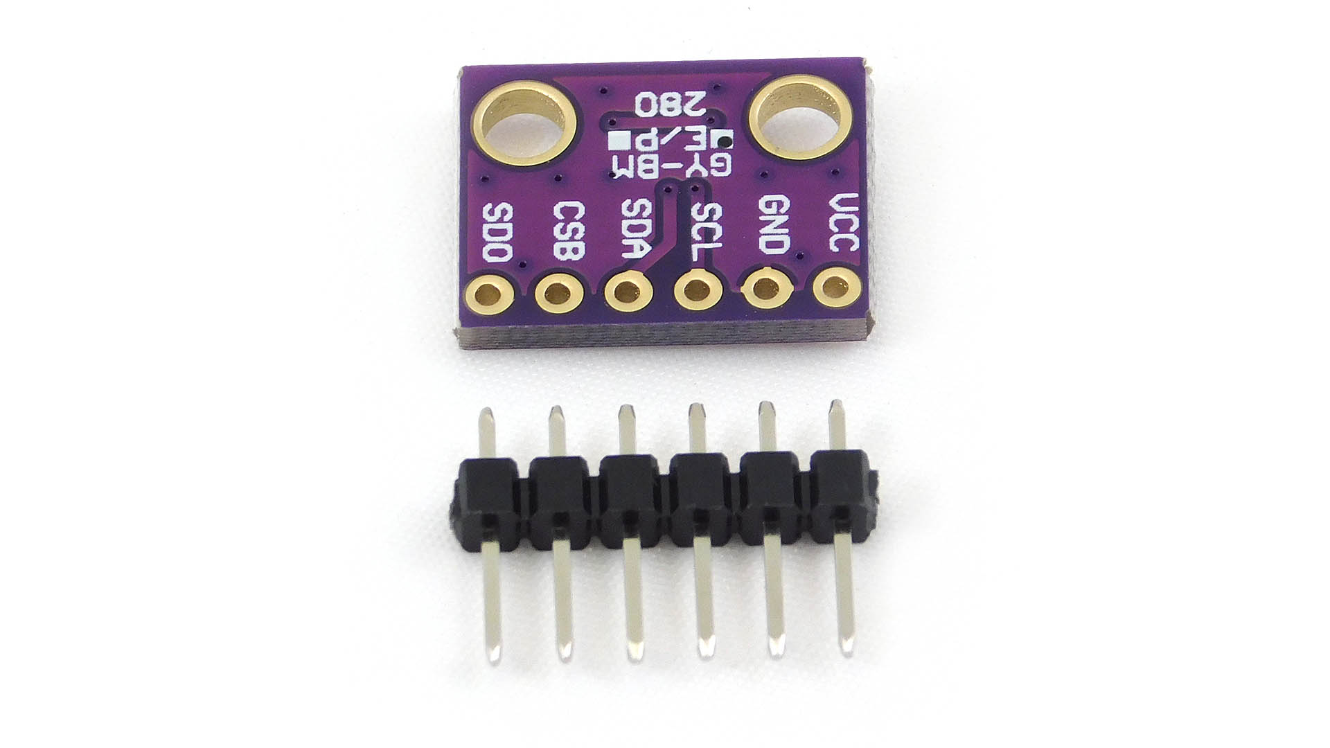
My BME280’s are the larger ones with 6 pins (‘3.3V version’).
I noticed that Adafruit BME280 library uses 0x77 as default I2C address while my Chinese BME280’s have 0x76 as default address (the Adafruit sensor boards probably use 0x77 as default address).
So for my Chinese BME280 sensor boards I explicitly have to specify the proper I2C address when calling BME280.begin() i.e. bme280.begin(BME280_ADDRESS_ALTERNATE, &Wire) or just bme280.begin(0x76, &Wire).
Defined are:
BME280_ADDRESS (0x77)
BME280_ADDRESS_ALTERNATE (0x76)
I think you mean the six pin BME280 board but that image is a BMP280 board. ![]()
(Same PCB is used for both BMP280 and BME280 sensors.)
Your software could try both. Test is the sensor responds to 0x77 and if it does not respond then try the other address.
BOSCH datasheet warns to not leave the address selection pin floating, so it may be worth checking if the pcb designer did his/her RTFM homework and took care of this…
The 7-bit device address is 111011x. The 6 MSB bits are fixed. The last bit is changeable by SDO value and can be changed during operation. Connecting SDO to GND results in slave address 1110110 (0x76); connection it to VDDIO results in slave address 1110111 (0x77), which is the same as BMP280’s I²C address. The SDO pin cannot be left floating; if left floating, the I²C address will be undefined.
LoRaMac-node for ESP32 available
Can be used for Heltec ESP32 LoRa products only
Essential parts of the source code are obfuscated (compiled to assembly).
“An unique license relate to Chip ID is needed, you can check your license here: Search ChipID relative License – Heltec Automation”
Great initiative but mixed feelings because of its closed character and license requirement per node. Applications using this library are limited to Heltec hardware which limits wider application
(therefore less attractive for developers). ![]()
![]()
![]()
![]()
![]()
![]()
Also see: Overview of LoRaWAN Libraries [HowTo] - #11 by bluejedi
Has anyone used it already?
I don’t think the ecosystem of Heltec hardware is worth to accept a vendor lock-in.
Meanwhile good old LMiC stack is close to a LORAWAN 1.0.3 certification, thanks to the great work by Terry Moore: https://github.com/mcci-catena/arduino-lmic
2 Likes
Correct.
Even with current developments on LMIC it would still be ‘nice’ to have LoRaMac-node implementations more widely available.
1 Like
I made a sketch for the TTGO-LoRa32-V2.1 (version T3_v1.6 20180606).
I am looking for people to test it. It has ABP and otaa activation. It also supports the OLED display. You can check it on: https://github.com/rwanrooy/TTGO-LoRa32-V2.1-TTN
ESP32-S2
Espressif recently introduced a new member of the ESP32 family: the ESP32-S2
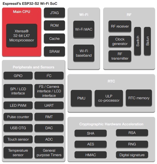
ESP32-S2 datasheet is available here
Comparison with regular ESP32
(Source: https://esp32.com/viewtopic.php?t=10632)
What do we gain over ESP32?
- Xtensa LX7
- USB FS OTG
- Support for larger external SPI RAM up to 128MB
- Support for larger external SPI Flash up to 1GB
- More GPIOs (39 gpio + 1 gpi, 22 rtcio)
- 14/15 ch Waterproof touch sense? & Proximity sensing
- Improved SPI (OSPI)
- Improved ULP (RISC-V)
- WiFi Indoor Positioning (802.11mc)?
- V2I (802.11p?)
- Lower cost
- External ram access from instruction cache
- Auto-zero ADC
- PSRAM encryption
What do we lose?
- Bluetooth
- ### Dual core ###
- RAM space (320KB vs 520KB)
- ROM space (128KB vs 448KB)
- UART (2 vs 3)
- SDMMC
- MCPWM
- Ethernet
- I2S (1 vs 2, no PDM)
- RMT (4ch vs 8ch)
- PCNT (4 vs 8)
ESP32-SOLO-1
ESP32-SOLO-1 is a new Espressif module that is based on the new ESP32-S2.
Available here:
2 Likes
Hi bluejedi,
yes I have used this source code and board from Heltec, but I found it a little bit complicate due to make for each board a new compilation because of the unique license. Also after some good joins during test also the OTAA fails. Why I can’t found out. ADB work with lmic fine.
Now I’m go to test deep sleep and OTAA as well.
I uses also the lmic from mcci-catena now.
I found two pin configuration for V2 of this board:
I uses:
//LMIC LoRa module pin configuration
//For Heltec Wifi LoRa 32 use:
const lmic_pinmap lmic_pins = {
    .nss = 18,
    .rxtx = LMIC_UNUSED_PIN,
    .rst = 14,
    .dio = {/*dio0*/ 26, /*dio1*/ 35, /*dio2*/ 34}
};
and also I found:

//LMIC LoRa module pin configuration
//For Heltec Wifi LoRa 32 use:
const lmic_pinmap lmic_pins = {
    .nss = 18,
    .rxtx = LMIC_UNUSED_PIN,
    .rst = 14,
    .dio = {/*dio0*/ 26, /*dio1*/ 34, /*dio2*/ 35}
};
only changed in dio 34 and 35. Why? For me it seems to be clear the first one. Have others other experience?
Also OTAA fails because the board misses the agreed downlink. Also in ADP downlink seems to be critical.
Perhaps I’ll make LMIC with interrupt:
https://www.thethingsnetwork.org/forum/t/big-esp32-sx127x-topic-part-1/10247/11
Hope to help other to go further with his project and this board.
1 Like
A real pity that their LoRaMac-node port to ESP32 is not open / not available for general use. So there still appear to be issues with it. Because not open there will be much less people that are going to test it and less people to report any issues.
Yes for Heltec WiFi LoRa 32 V2 the first you listed is correct (the second is incorrect):
const lmic_pinmap lmic_pins = {
  .nss = 18,
  .rxtx = LMIC_UNUSED_PIN,
  .rst = 14,
  .dio = {/*dio0*/ 26, /*dio1*/ 35, /*dio2*/ 34 }
};
Also note that GPIO ports used for I2C OLED display are not the standard ones for I2C:
Display-SDA = 4 (not 21, SDA=21)
Display-SCL = 15 (not 22, SCL=22)
Display-RST = 16
1 Like
Check out latest paxcounter version 1.8.0, it runs LMiC controled by hardware Interrupts. I found the bug in MCCI LMiC which broke this feature last week and made a Pull Request, this was merged meanwhile.
1 Like