maybe … if you have a link ? 
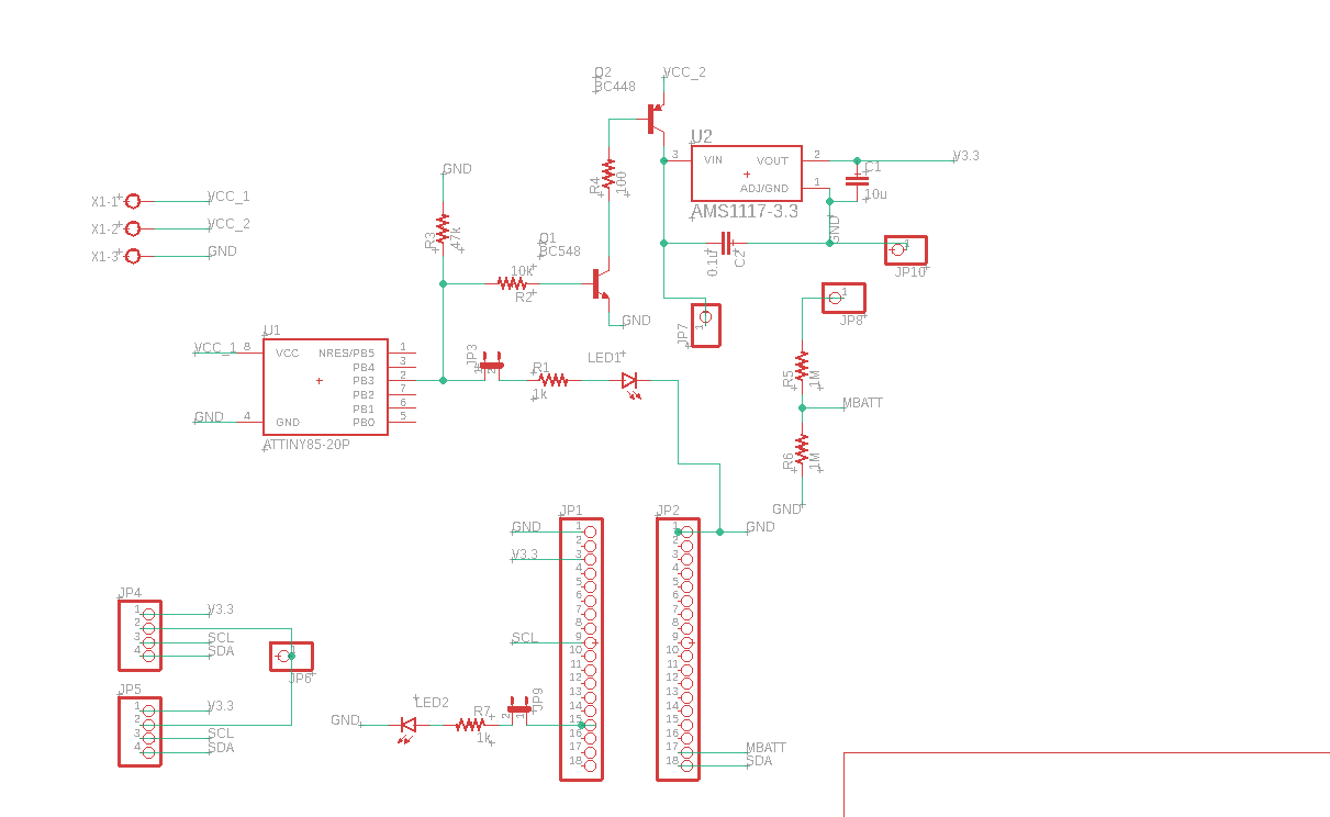
Battery control circuit:
Just replace the BC448 for one C32740
Attiny85 Code:
#include <avr/sleep.h>
#include <avr/wdt.h>

#ifndef cbi
#define cbi(sfr, bit) (_SFR_BYTE(sfr) &= ~_BV(bit))
#endif
#ifndef sbi
#define sbi(sfr, bit) (_SFR_BYTE(sfr) |= _BV(bit))
#endif

int pinLed = 3;
volatile boolean f_wdt = 1;

void setup(){
  pinMode(pinLed,OUTPUT);
 // approximately 4 seconds sleep
  //setup_watchdog(8);
}

void loop(){
  if (f_wdt==1) {  // wait for timed out watchdog / flag is set when a watchdog timeout occurs
    f_wdt=0;       // reset flag

    digitalWrite(pinLed,HIGH);  // let led blink
    delay(2000);
    digitalWrite(pinLed,LOW);

    pinMode(pinLed,INPUT); // set all used port to intput to save power

    // Parameter should be multiple of 8 and should be grater than 8
     sleep_tiny(8);
    //sleep_tiny_750();

    pinMode(pinLed,OUTPUT); // set all ports into state before sleep
  }
}

// set system into the sleep state
// system wakes up when wtchdog is timed out
void system_sleep() {
  cbi(ADCSRA,ADEN);                    // switch Analog to Digitalconverter OFF
 // setup_watchdog(8);;
  set_sleep_mode(SLEEP_MODE_PWR_DOWN); // sleep mode is set here
  sleep_enable();
  sleep_mode();                        // System sleeps here
  sleep_disable();                     // System continues execution here when watchdog timed out
  sbi(ADCSRA,ADEN);                    // switch Analog to Digitalconverter ON
}

// 0=16ms, 1=32ms,2=64ms,3=128ms,4=250ms,5=500ms
// 6=1 sec,7=2 sec, 8=4 sec, 9= 8sec
void setup_watchdog(int ii) {

  byte bb;
  int ww;
  if (ii > 9 ) ii=9;
  bb=ii & 7;
  if (ii > 7) bb|= (1<<5);
  bb|= (1<<WDCE);
  ww=bb;

  MCUSR &= ~(1<<WDRF);
  // start timed sequence
  WDTCR |= (1<<WDCE) | (1<<WDE);
  // set new watchdog timeout value
  WDTCR = bb;
  WDTCR |= _BV(WDIE);
}

// Watchdog Interrupt Service / is executed when watchdog timed out
ISR(WDT_vect) {
  f_wdt=1;  // set global flag
}

void sleep_tiny (int seconds){

  int m = 8;
  int t = seconds/m;
  for (int i=0;i<t;i++){
    setup_watchdog(m);
    system_sleep();
  }

}


void sleep_tiny_750 (){

  for (int i=4;i<6;i++){
    setup_watchdog(i);
    system_sleep();
  }
If you need anything else let me know!
1 Like
Guys,
I really need a help with my esp heltec board. I have two main problems
1 - My receive node stops to work after a few minutes. I’m using LoRa.parsePacket();
2 - If I increase the message size ( like 15 bytes) it stops to receive, when I increase the message the receiver stops to work more often too.
Please can anyone help me with this? Im blocked for weeks. =/
Without link to the code running on your Heltec board there won’t be any answers possible here.
Hello Verkehrsrot,
Even with the OLED_LoRa_Receiver and OLED_LoRa_Sender examples I’m having this kind of problem.
Problem 1:
My receive just stops to receive, it’snt blocked, but LoRa.parsePacket() just return zero after a while, when a reset the module it start to receive again.
Problem 2:
For the size of the packet how many bytes is the maximum? I saw in the datasheet of SX1276 that we could send a packet with 256 bytes but Im not even close and the receive start to lose a lot of packages when the package has a size like 15 bytes.
Dou you guys think that it could be my board? How many bytes did u send whitout a considerable packet loss.
Hello all,
First thanks to bluejedi and all the other contributors, I am new to arduino and believe i have made a massive stuff up! In my eagerness to test i have missed changing the pin settings in my ttn-otaa sketch setup, for TTGO v1 and believe this has now killed my access from the mounted USB port.
Are my assumptions correct? if so could i use a ftdi adapter to recover the device?
I have configured my spare TTGO Lora V1 with correct pins and have worked out frequency for AU and now have it showing up on ttn site as a activation attempt it dose not appear to activate.
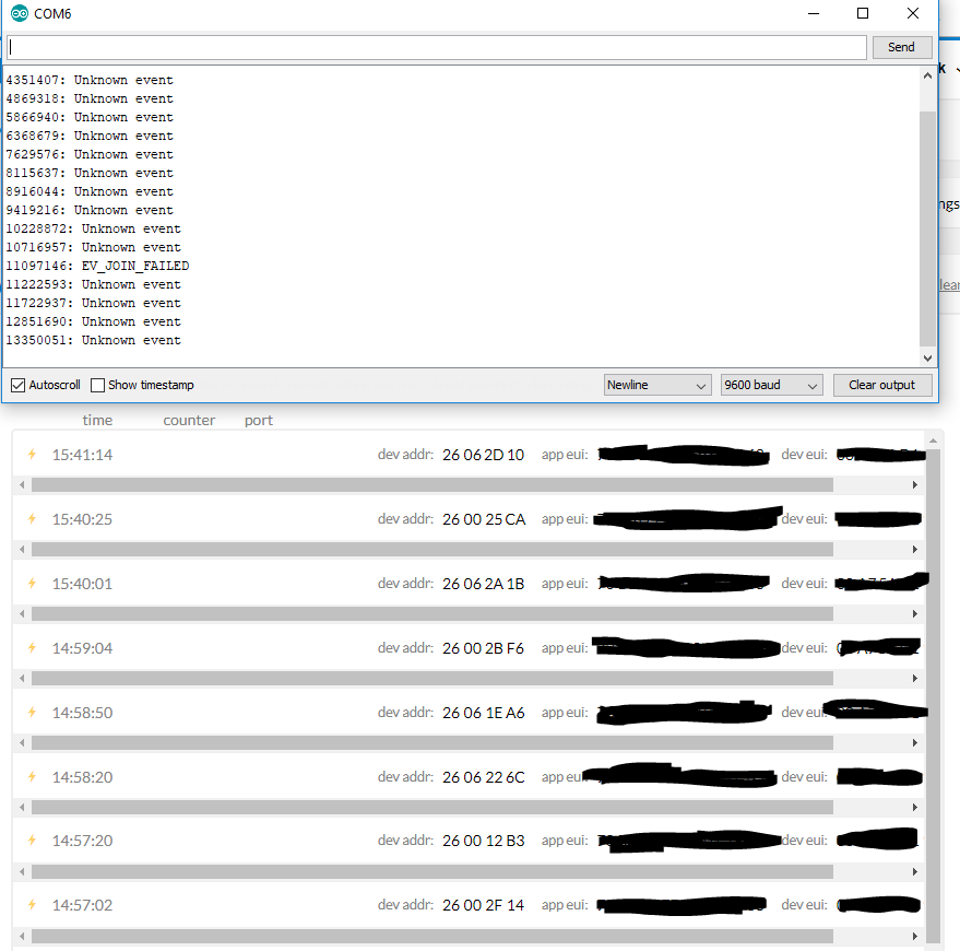
Why is the Dev addr: different each time?
would appreciate a point in a direction as i now seam to be stuck in a loop
Thanks Oztechgeek
they seem all failed OTAA attempts. Is the node functioning correctly with ABP? Are you using a real gateway or a single channel?
1 Like
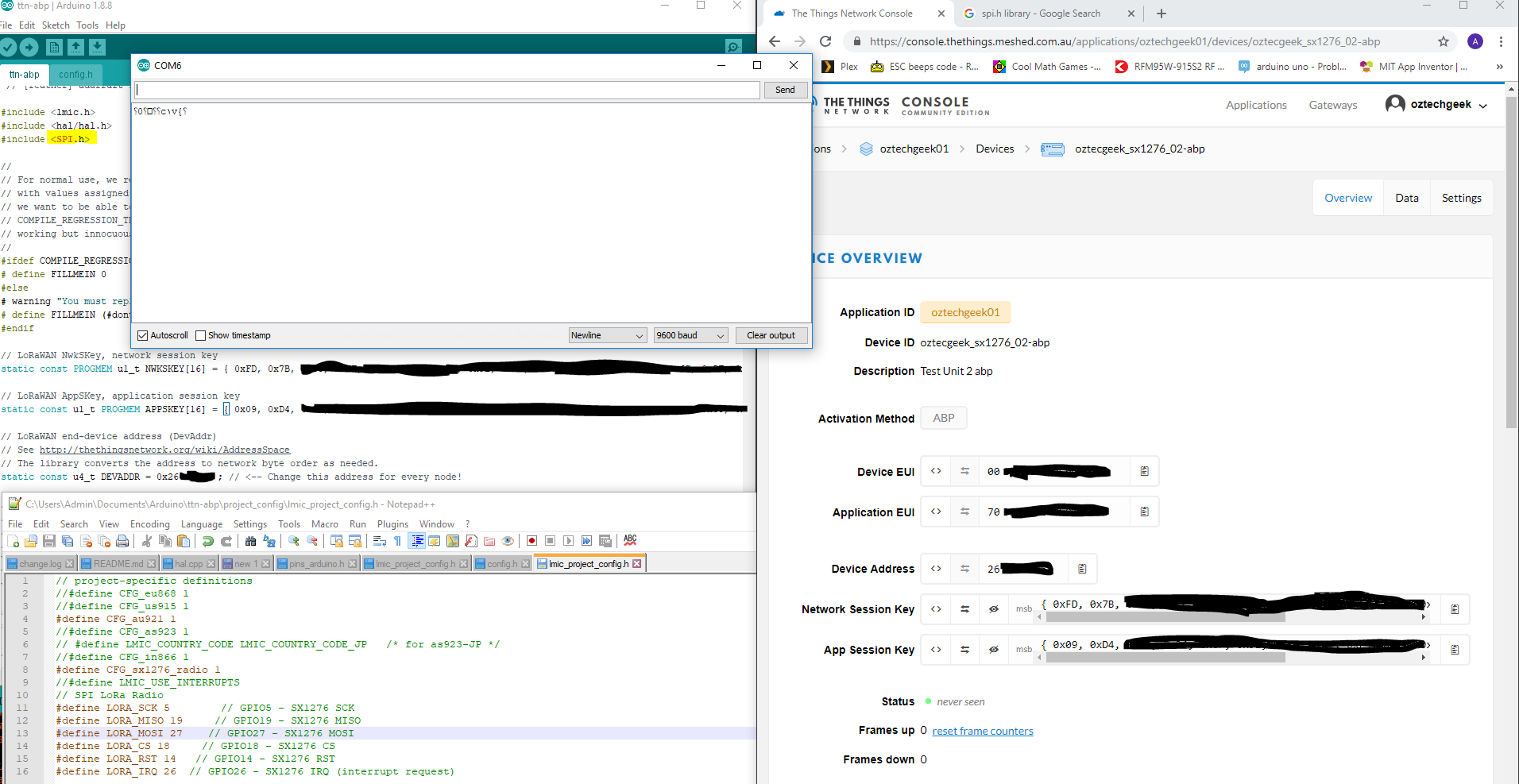
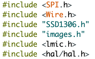
No it is not, all i get is garbage from the console, i have noted that SPI.h is showing red and wonder if this has something to do with it…
It is a real gateway.
ABP:
Thanks
No, that’s fine; that’s just bad syntax highlighting triggered by the leading uppercase character in the name. This works for me (for a different device):
As for garbage in the console: does the baud rate of 9600 match the value in the code?
Your OTAA example indeed shows that the node transmits the Join Request just fine, and that TTN received and accepted it, as it assigned a DevAddr (which indeed will be different for each accepted join). In the gateway’s Traffic page in TTN Console you should also see a green icon for the Join Accept, for the gateway that TTN selected to transmit that, but I’m afraid your node did not receive that downlink.
What SF is the Join Request using? Do you see the green Join Accept? Please show its details. As the OTAA Join Request works, ABP should work too, as ABP does not need any downlinks at all. Be sure to keep at least a few meters between node and gateway. And see LMIC_setClockError: Over-the-air-activation OTAA with LMIC - #36 by matthijskooijman.
FYI: Each (most) Arduino libraries have a keywords.txt file which is used by the editor for syntax highlighting.
The syntax highlighting is rather dumb however. It is based on text compare and involves no or little intelligence from the compiler about the actual source code structure and therefore also highlights in the wrong places (like in the include statements).
1 Like
Hi,
Thanks for that magnificent thread.
I’ve encountered a problem with the TTGO Lora32 V2 while trying to use it as a node (it said Failure on serial port), finally I solve it tweaking the code in the library “hap.cpp”, I had to manually put the pins for “SPI.begin(5,19,27,18);”.
Is that a normal case scenario? Any workaround without having to touch library code?.
Thanks
2 Likes
What library is hap.cpp part of?
Having to modify library source code like this is not normal and indicates a design smell. In practice however, many libraries for the Arduino framework suffer from this problem.
Initializing shared resources like the I2C and SPI busses is the responsibility of the application, not the responsibility of some library (e.g. for sensors or displays).
Well designed libraries shall adhere to design principles like separation of concerns and dependency inversion to prevent these types of issues. One should be able to use a library only through it’s API, without having to modify its source code for external dependencies.
Many existing libraries initialize (hard-coded) the I2C and SPI bus, while these communication busses are shared external resources. Such libraries act like they own these resources while they do not. In practice I2C and SPI busses are often shared with other peripherals (that use other libraries).
The Arduino platform itself is not exactly of help here. For instance Wire.begin() can be called with different parameters for initializing the Wire library (I2C) but there is no option to check if the Wire library (i.e. the global Wire instance of the TwoWire class) was already initialized before (but is not an excuse for other libraries to call Wire.begin()).
The Wire and SPI libraries can even be hardware platform (with related Arduino core) dependent. Meaning that there may be different parameter (options) for different platforms. The average library shall (must) not (have to) be aware of such details.
(E.g. on AVR MCU’s Wire.begin() has a single optional parameter ‘slaveid’ which is required to let the MCU act as client on the I2C bus (instead as a master), but on the ESP8266 and ESP32 platforms clientmode is not supported but parameters can be specified for which (alternate) pins to use for SCL and SDA.)
Libraries should not initialize the I2C and SPI busses and leave that responsibility to the application. If not this will cause incompatibilities that may require ugly hacks as workarounds. Incompatibilities that can be prevented by proper design.
Hi,
I would like to say BIG THANKS to all commenting on this thread. I finally achieved to tweak the code and let run my ESP32 TTGO V1 working with TTN (sending DHT sensor data) and a Single Channel GW.
I shared a short video showing working on my Twitter account: https://twitter.com/AlexCorvis84/status/1101208767339945989
Thank you all!! Awesome helpful thread!
4 Likes
Has someone try to use ULP core ?
Tried the suggested lib here : https://www.youtube.com/watch?v=-QIcUTBB7Ww
but the lib is kind of a not ready… e.g. did not managed to install it and make it work wit latest ESP32 core…
Any one with suggestion with reasonable 3G/4G module for ESP32 ?
Trying to build a 3G/4G Gateway…
Has anyone been able to use an external device over the SPI bus ? I have a Heltec 32 Lora v2 and am trying to use MAX7219 led matrix. I had it working on an esp8266 based board but I can’t get it to work on the this Lora board. There appears to be two spi busses VSPI and HSPI. I tried to use the VSPI bus but it didn’t work. I also tried using pins gpio 36,37,38 for CLK, MOSI, CS and that didn’t work either. I know in theory I would have to use the led matrix and the LoRa functions one at a time because they would be on the same bus but it’s confusing because according to the pinout V_SPI_CLK is used as the LoRa_CS pin and the V_SPI_CSO is used for the LoRa_ SCK. Seems backwards to me.
I have had a LoRa device and a micro SD card working on the same bus.
Which LoRa TTN library are you using ?
I designed my own pcb for the ESP32 + RFM95 for the Lorawan network. My design is based on using the Lolin D32 combined with a RFM95.
I managed to get a deep sleep current for around 240uA while deep sleeping. I’m pretty happy with the first results. It should still be possible to achieve lower results, because Lolin D32 alone uses around 70uA while in deep sleep.
So the remaining 170uA is being used by the RFM95 while the ESP32 is in deep sleep. I hope I can bring it further down. I already tried to putting the SS pin (GPIO4) to HIGH before going to deep sleep and holding it HIGH with the use of the RTC part of the ESP32:
LMIC.shutdown();
digitalWrite(4, HIGH);
esp_err_t rtc_gpio_hold_en(GPIO_NUM_4);
The library I am using to control the RFM95 is this one which support deep sleep:
Anybody got any suggestions what I could try more?
1 Like
mmm, much easier to strive for low current when your checking the design out on breadboard.
There are some comments about reducing power consupmtion of ESP32 and LoRa devices in the posts below;
http://www.loratracker.uk/?p=810
http://www.loratracker.uk/?p=817
1 Like