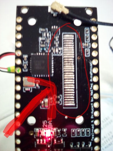
I am working with a TTGO Lora32 V2 and have tried the examples from the Arduino-LIMC library by Matthijs Kooijman. It looks like I have the board working: with both the ABP and OTAA examples I see action on my gateway. In ABP mode only one hit, in OTAA mode I see a join request, a join accept and then an uplink. However: this happens only once on power up or when I hit the reset button. I assumed that I would see a continuous series of messages. The code says that the TX interval is 60 seconds, but nothing happens. To be clear: in both ABP and OTAA only once a packet is handled by the gateway.
When I go to the application I can see how long ago the board was powered on, but both the Frames up/Down counters say “0”
Am I wrong in my assumption that I should see a message every 60 seconds? My gateway is made of a iC880A-SPI concentrator board with a Raspberry. I know that the gateway works since when I power up another node (a LSN50 I see a continuous stream of packets coming in.
Thanks! I tried what he did in the link. I tried adding 20k pull-up resistors on Mosi, Miso, SS and CLK. I now got the standby consumption reduced to 154uA!
I have two Heltec Lora V2 boards and even though I’ve been having some intermittent consistency problems I’m excited today because I got successful 2 way data transmission at 12.4 miles distance. https://photos.app.goo.gl/UBVdm1aq75r3NRxHA
Higher value resistors will not improve the current consumption in sleep as these lines are only floating. However, if you have these pull ups connected to the supply rail it means that the current consumption would be higher when the processor is not in sleep state.
Is anyone else having issues while using the Heltecs board for both rx and tx ? Whenever I use one of these boards to send and receive via LORA they seem to get stuck in RX mode or a TX mode ? A board will receive a “request” packet and then try to transmit a data packet. The packet seems to send but doesn’t actually send. If I reset the entire board then transmitting starts working again. I’ve tried resetting just the LoRa module but that doesn’t seem to help. When I set up the devices so that they only ever send or receive (but not both) then they work just fine with no hiccups. I’m currently using the radiohead library to operate the LoRa radios.
It does sound like an issue with the Radiohead library on ESP32, not sure if its 100% supported. You might find more users of that point to point LoRa library over in the Arduino forums.
I edited the ttn-abp/otaa example, from lmic library, adding the correct definitions for Oled pins and LoRa module for the ESP32 Heltec v2: https://goo.gl/hKL1mj
Plus if you uncomment #define DEBUG_OLED you can see the the Serial output on the Oled screen.
Yes, it should be possible. According to the schematics, the RX/TX pins are connected to a CP2102 USB-UART bridge controller. If you have USB-UART module like this below you can connect to the ESP32.