Yes, other board, but the same Software and EV_TXCOMPLETE occurs.
Visually, both boards look the same. Both boards labeld as T3_V1.6.
Over the next few days I expect another delivery, then I will continue to test that.
Greetings
Ernst
Yes, other board, but the same Software and EV_TXCOMPLETE occurs.
Visually, both boards look the same. Both boards labeld as T3_V1.6.
Over the next few days I expect another delivery, then I will continue to test that.
Greetings
Ernst
Hello,
Sorry for my bad english.
I bought two LoRa TTGO.
I has loaded sender and receiver programs and I have connection.
But de RSSI is -80 with antennas close.
If I go to another room i lose the conexion.
Is possible antennas are wrong?
Could you recomend antenna.
I’m interested connect for home made weather station at 5-7km with no lineal vison.
Best regards,
David.
Welcome to the forum.
You say ‘close’ but we dont know what ‘close’ is.
If the units are say within 1m and the RSSI is -80dBm, something is wrong, faulty devices or antennas, even a short bit of wire as an antenna should work better at that distance.
Be aware that this is a support forum for The Things Network (TTN) devices and not a general purpose forum for LoRa devices.
I’m sorry but not found any other forum for ask about this.
Closed <1cm
With 1cm and -80dbm you either have defective hardware or the frequencies do not match.
LOL 
I have a Heltec (quite similar to the TTGO). Uplink (join) traffic is received by by gateway on SF7 from 3 km distance with our small town in between. But the join never completes. It will only complete on SF11 when I am 50 m from the gateway in direct line of sight of the gateway’s antenna. I removed the display to get to the LoRa radio. Looks like a capacitor is missing in the reception network to the antenna switch.
Bugger. The ESP32 and the display work nicely though  .
.
Huge thanks to you @DaveCalway . I wish @bluejedi would add this pin configuration to the summary at the top. It is 100% accurate for the latest ESP32 Heltec v2 HTIT-WB32LA that has the “V2” stamp next to the antenna connector.
Hello Guys.
I have problem with ttn-abp example.
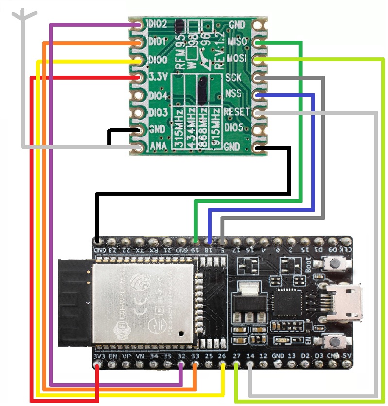
I have RFM95W-868-S2 + ESP32-DevKitC + antenna 868MHz SMA
// Pin mapping
// Adapted for Feather M0 per p.10 of [feather]
const lmic_pinmap lmic_pins = {
.nss = 18, // chip select on feather (rf95module) CS
.rxtx = LMIC_UNUSED_PIN,
.rst = 14, // reset pin
.dio = {26, 33, LMIC_UNUSED_PIN}, // assumes external jumpers [feather_lora_jumper]
// DIO1 is on JP1-1: is io1 - we connect to GPO6
// DIO1 is on JP5-3: is D2 - we connect to GPO5
};
And I get on Starting Failure:
Starting
FAILURE
C:\Users\ladislav.lucivjansky\Documents\Arduino\libraries\MCCI_LoRaWAN_LMIC_library\src\lmic\oslmic.c:53
50: void os_init() {
51: if (os_init_ex((const void *)&lmic_pins))
52: return;
53: ASSERT(0);
54: }
Have you and idea what i do wrong?
Might be a problem with your code.
Where for instance are you defining the SPI pin numbers for MOSI, MISO and SCK ?
I see quite a few things:
RESET is connected to pin 24 while in the pin mappings it is specified as 14.
“Pin mapping adapted for Feather M0 per p.10 of [feather]”,
“// DIO1 is on JP1-1: is io1 - we connect to GPO6”,
“// DIO1 is on JP5-3: is D2 - we connect to GPO5”.
These remarks do not relate to your ESP32-DevKitC because it is not compatible with Adafruit Feather M0.
In the wiring diagram DIO2 is wired but it is not configured in the pin mapping (LMIC_UNUSED_PIN instead of 32).
Analysis:
Your SPI pin wiring is incorrect.
The pins wired for SPI interface are not the proper SPI pins for your ESP32-DevKitC board.
You may possibly also not have selected the proper ESP32 board in your Arduino (or PlatformIO) IDE. The matching board definition to use for ESP32-DevKitC probably is “DOIT ESP32 DEVKIT V1”, which defines the SPI ‘pins’ (GPIOs) as follows:
    static const uint8_t SS    = 5;
    static const uint8_t MOSI  = 23;
    static const uint8_t MISO  = 19;
    static const uint8_t SCK   = 18;
If the wrong board is selected the pin definitions for the SPI interface will most often be incorrect, in which case the software cannot communicate with the RFM95 module which would explain the FAILURE message.
When using the LMIC library, for normal LoRaWAN operation DIO2 is not required so the connection to DIO2 can be removed.
Questions:
Suggestions:
Wire MISO, MOSI, SCK and (N)SS according to above SPI pin definitions.
In the IDE use board definition “DOIT ESP32 DEVKIT V1”.
Correct '.rst = 14, // reset pin' so that it matches the actual pin (GPIO) wired to RESET.
Change '.nss = 18, // chip select on feather (rf95module) CS' to
.nss = 5
or my personal preference, which indicates that the standard SPI SS pin/GPIO is used which also makes it easier to port the code to a different board (because part of standard board definitions):
.nss = SS
Remove the connection to DIO2.
Please read How do I format my forum post? [HowTo] for how to format sourcecode in a post.
board is esp32 devkitc v4 espressif
https://www.espressif.com/en/products/hardware/esp32-devkitc/overview
IDE is Arduino IDE 1.8.9
Selected board is ESP32 DevModule
new config:
DIO2 removed
Selected DOIT ESP32 DEVKIT V1
SS = 5;
MOSI = 23;
MISO = 19;
SCK = 18;
RST = 14;
DIO1 = 26;
DIO2 = 33;
serial monitor:
Starting
10619: EV_TXSTART
Packet queued
199158: EV_TXCOMPLETE (includes waiting for RX windows)
3949179: EV_TXSTART
Packet queued
4135922: EV_TXCOMPLETE (includes waiting for RX windows)
seems better… 
That’s an understatement. ![]()
Should probably be:
DIO0 = 26;
DIO1 = 33;
yes
DIO0 = 26;
DIO1 = 33;
There was a mismatch when posting…
Indeed, SPI decivices do seem to work a lot better when connected to MOSI, MISO and SCK.
“ESP32 Dev Module” should work as well but does not define LED_BUILTIN.
maybe a stupid question, but where i can find Device EUI?
Its written on RF chip?
If yes, what code system is on chip and what code system requires TTN?
this topic doesnt exist https://www.thethingsnetwork.org/forum/t/how-to-find-the-deveui-on-a-rfm95/3899
you let TTN generate it in the console and after you add this to your code
[Solved]
Hi, after reading quite a bit and trying everything I could I decided to ask for help here to see if we can make the node work…
I have a TTGO Lora32 V2 board, I have the “Heltec WiFi LoRa 32” selected on my arduino IDE and I’m using the following library: GitHub - mcci-catena/arduino-lmic: LoraWAN-MAC-in-C library, adapted to run under the Arduino environment
The pin mapping is
.nss = 18,
.rxtx = LMIC_UNUSED_PIN,
.rst = 14,
.dio = {26, 33, 32}‘’
I’m trying to make the “hello world” example work.
ABP
In the serial monitor I can see:
EV_TXSTART
Packet queued
4135922: EV_TXCOMPLETE (includes waiting for RX windows)
SOLVED: By setting the frecuency correctly on /project_config/lmic_project_config.h
OTAA
In serial monitor apears:
rst:0x1 (POWERON_RESET),boot:0x13 (SPI_FAST_FLASH_BOOT)
configsip: 188777542, SPIWP:0xee
clk_drv:0x00,q_drv:0x00,d_drv:0x00,cs0_drv:0x00,hd_drv:0x00,wp_drv:0x00
mode:DIO, clock div:2
load:0x3fff0018,len:4
load:0x3fff001c,len:1100
load:0x40078000,len:9232
load:0x40080400,len:6412
entry 0x400806a8
The payload is delivered correctly but nothing appears on the serial monitor, only the message above, is that right?
Is that library known to work with ESP32 ?