Hi, i recieved board version 1.3 for which I couldnt find any information at all - here or event on link you provided.
according to reply from BSFrance support for 1.3. version : No solder pad need to be soldered for using the board, DIO1 is closed by default if you need to use LMIC, also compared to V1.2 and except for the sensors options that are not mounted on your particular board the difference is that the LiPo charger and the voltage divider for battery monitoring are controlled by a MOS from PB0 (active low).
It seems you managed to program the board.
I don’t know v1.3, I can only guess from previous version.
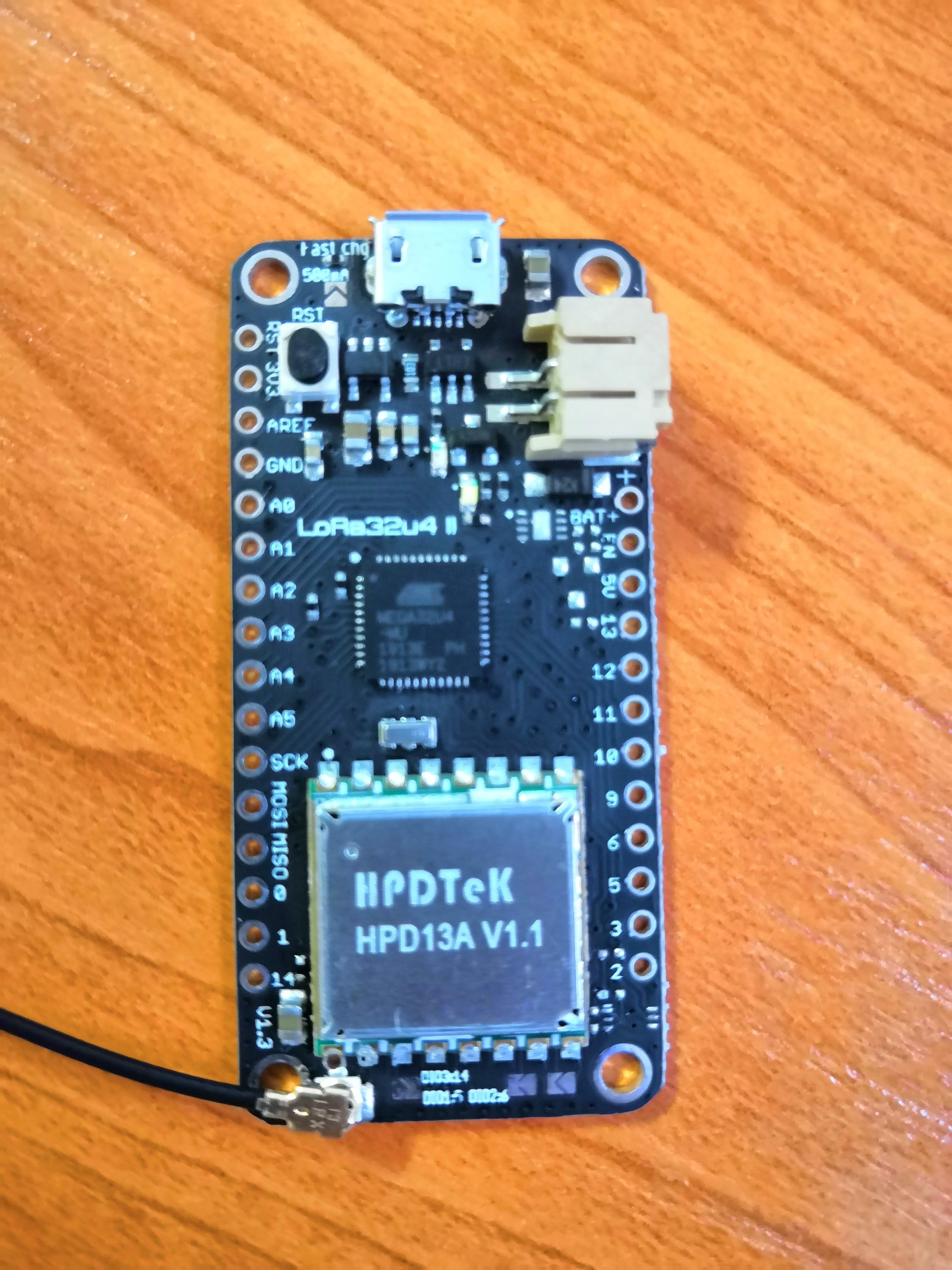
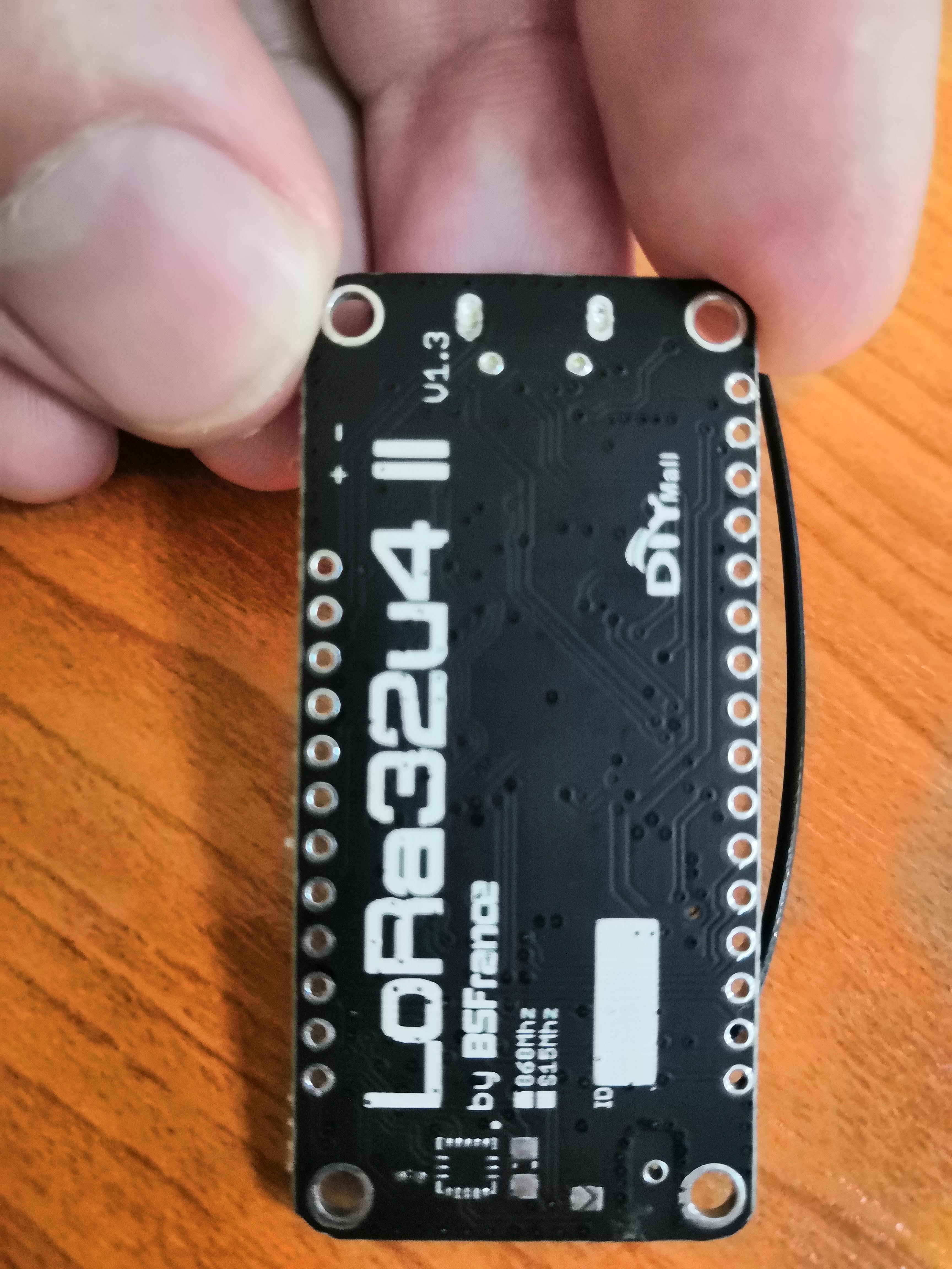
To avoid missunderstanding , I need you to share a front and back picture from board.
Is there solderpads between lora module and Atmega32u4? How are they connected?
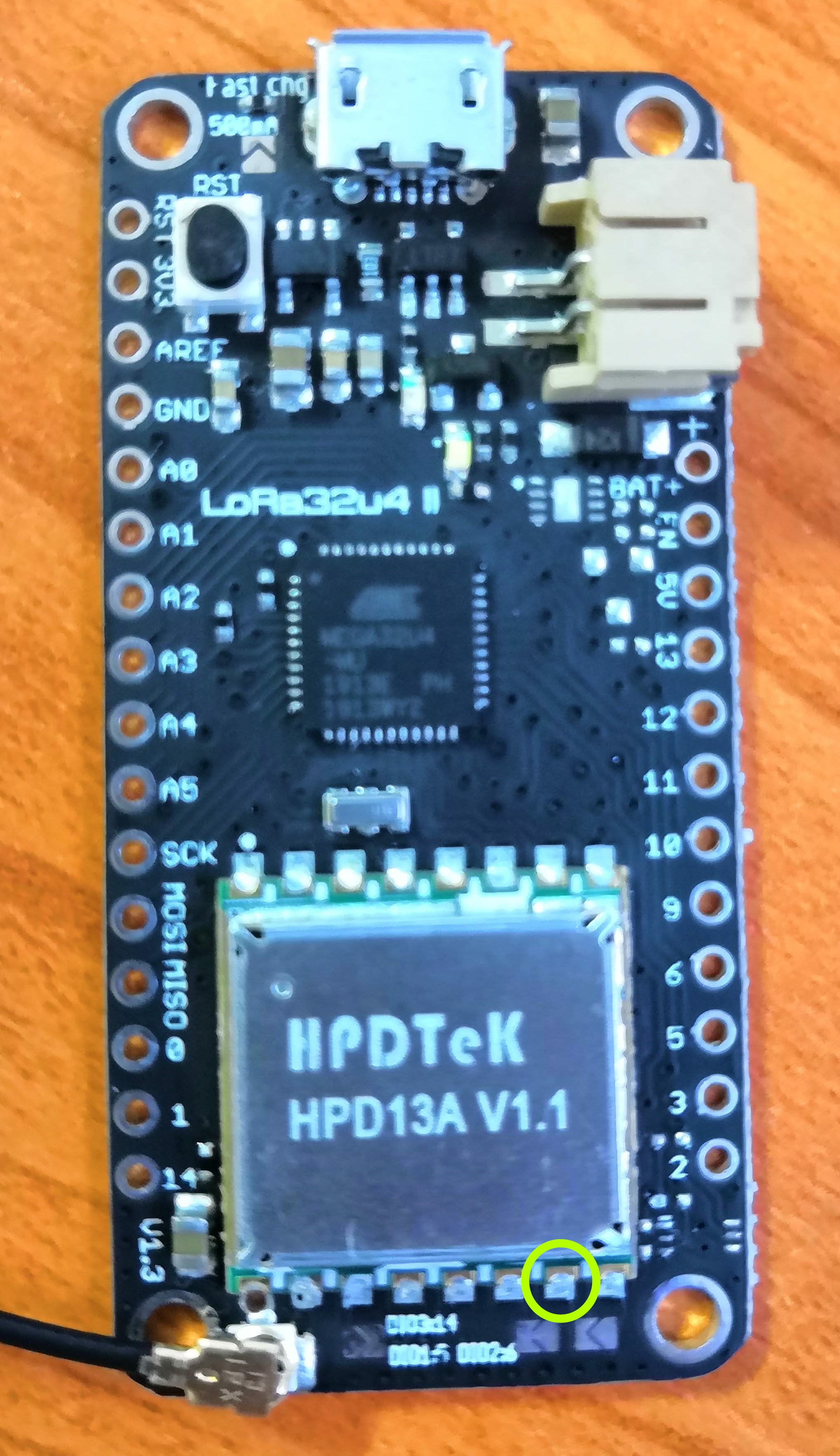
If I remember well, the circled pin is LoRa module “[D]IO1”.
BSFrance told you that “DIO1 [was] closed by default”. So, you have to find which board pin it is connected to.
A continuity check should do the job. Also check those 3 V shaped pads, this could help too!
Then, you will simply adapt DIO1 in lmic_pinmap accordingly :
{
.nss = 8,
.rxtx = LMIC_UNUSED_PIN,
.rst = 4,
.dio = {/ dio0 / 7, / dio1 / 1, / dio2 / LMIC_UNUSED_PIN}
};
Hope it will help!
All,
I’m trying to get my LoRa32u4 II (v1.2) up and running, but I’not even able to program the device. I trying to load the ttn-abp example using Arudino IDE 1.8.4 on Linux.
Unfortunately, programming fails with
avrdude: Device signature = 0x3f0d0d
avrdude: Expected signature for ATmega32U4 is 1E 95 87
Double check chip, or use -F to override this check.
I have udev rules installed as recommended. Pressing the reset button and releaser when the programmer looks for the port.
Any advice what I’m doing wrong here?
Thanks a lot!
- Stefan
… in addition to above:
Trying to upload and double-press the reset button results in
Reading | ################################################## | 100% 0.00s
avrdude: Device signature = 0x1e9587 (probably m32u4)
avrdude: reading input file "/tmp/arduino_build_70641/ttn-abp.ino.hex"
avrdude: writing flash (23842 bytes):

Writing | ########avrdude: error: programmer did not respond to command: set addr
####avrdude: error: programmer did not respond to command: set addr
Any hints?
Hi!
I remember you have to double tap reset button to switch in programming mode.
That’s sometimes not that easy under windows. I know nothing on Arduino IDE under linux.
Isn’t 1.8.4 a bit old now?
Hello,
I had the same problem with my LoRa32u4 1.2 on Linux (Ubuntu 18.04). What I did was :
-Install udev rules (as you did)
-Remove modemmanager (I saw this on another obsure forum topic, and I think thit did have an influence on uploading the program to the board)
-Use “AVRISP mkll” Programmer (from the Tools menu).
Hope it will help.
1 Like
Settings for BSFrance LoRa32u4 II v1.3
Click here to go back to the topic start
BSFrance has not yet updated their documentation and Arduino core since LoRa32u4 II v1.1.
Like previously for version v1.2 we will have to do our own research for v1.3 again.
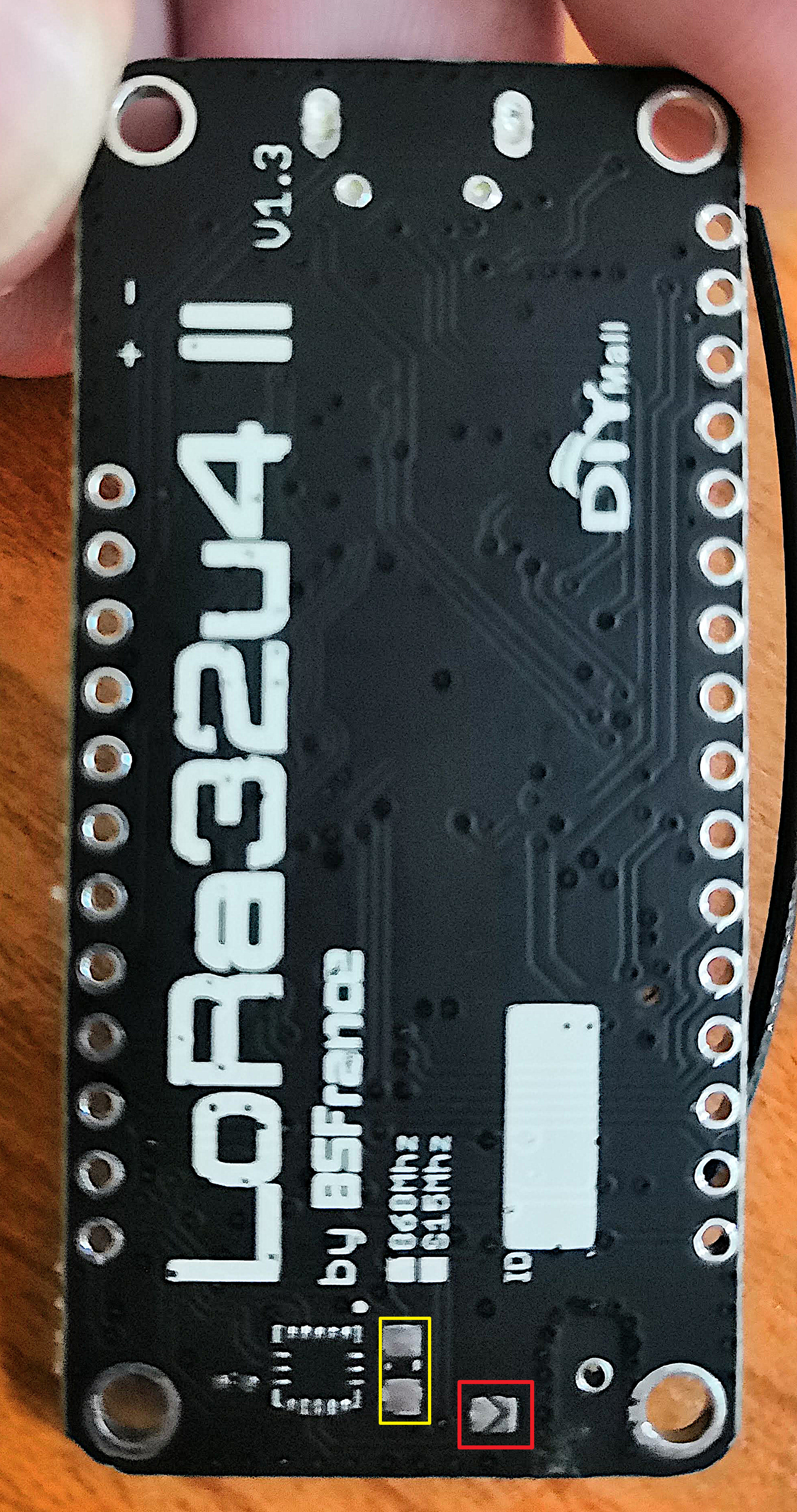
I don’t have the board but from @fanysoft’s pictures of the LoRa32u4 II v1.3 board I was able to make the following observations and conclusions:
- There are 5 solder jumpers, one is default connected (closed) and the other four are not (open), four are labled and the one on the bottom side is not:
- DIO1 (default connected)
- DIO2
- DIO3
- Fast charging (will use a higher charge current for the Li-ion/LiPo battery)
- One on the bottom side, not labled (unclear what this is for) - There are several places on the board where components are not installed. This could be intended for adding additional (optional) components later, or may indicate a design change for which the PCB was not updated.
- There are two solder pads on the bottom side (but unclear what these are for).
If my analysis is correct (the pictures are out of focus and not very sharp) then:
- DIO1 is connected to digital pin 5 via (default connected) solder bridge (middle of 3).
- DIO2 is unconnected, can be connected to digital pin 6 via solder bridge (right of 3).
- DIO3 is unconnected, can be connected to digital pin 14 via solder bridge (left of 3).
With version v1.3 of the board the solder bridge pin mappings have been updated/changed.
On v1.2 of the board the solder pins unfortunately mapped DIO ports to digital pins that are already used for I2C, Tx and external interrupts. This now seems to have been fixed with v1.3.
The LMIC Arduino library needs DIO0 and DIO1 for the LoRa protocol (DIO2 to DIO5 are not needed).
DIO1 seems default connected to digital pin 5 (via solder bridge) and with previous versions of the board DIO0 was hard-wired to digital pin 7 which will probably be is the same for v1.3.
Mappings for previous versions of the board that are probably unchanged for v1.3:
NSS <----> digital pin 8
MOSI <----> digital pin 16
MISO <----> digital pin 14
SCK <----> digital pin 15
RST <----> digital pin 4
DIO0 <----> digital pin 7
So for the BSFrance LoRa32u4 v1.3 board (manufactured by DIYmall) you should be able to use the following pin mappings for LMIC in your Arduino code:
Pin mappings for LMIC
const lmic_pinmap lmic_pins = {
  .nss = 8,
  .rxtx = LMIC_UNUSED_PIN,
  .rst = 4,
  .dio = {/*dio0*/ 7, /*dio1*/ 5, /*dio2*/ LMIC_UNUSED_PIN}  //
};
For V1.3 pinout see below post.
Pictures (annotated)
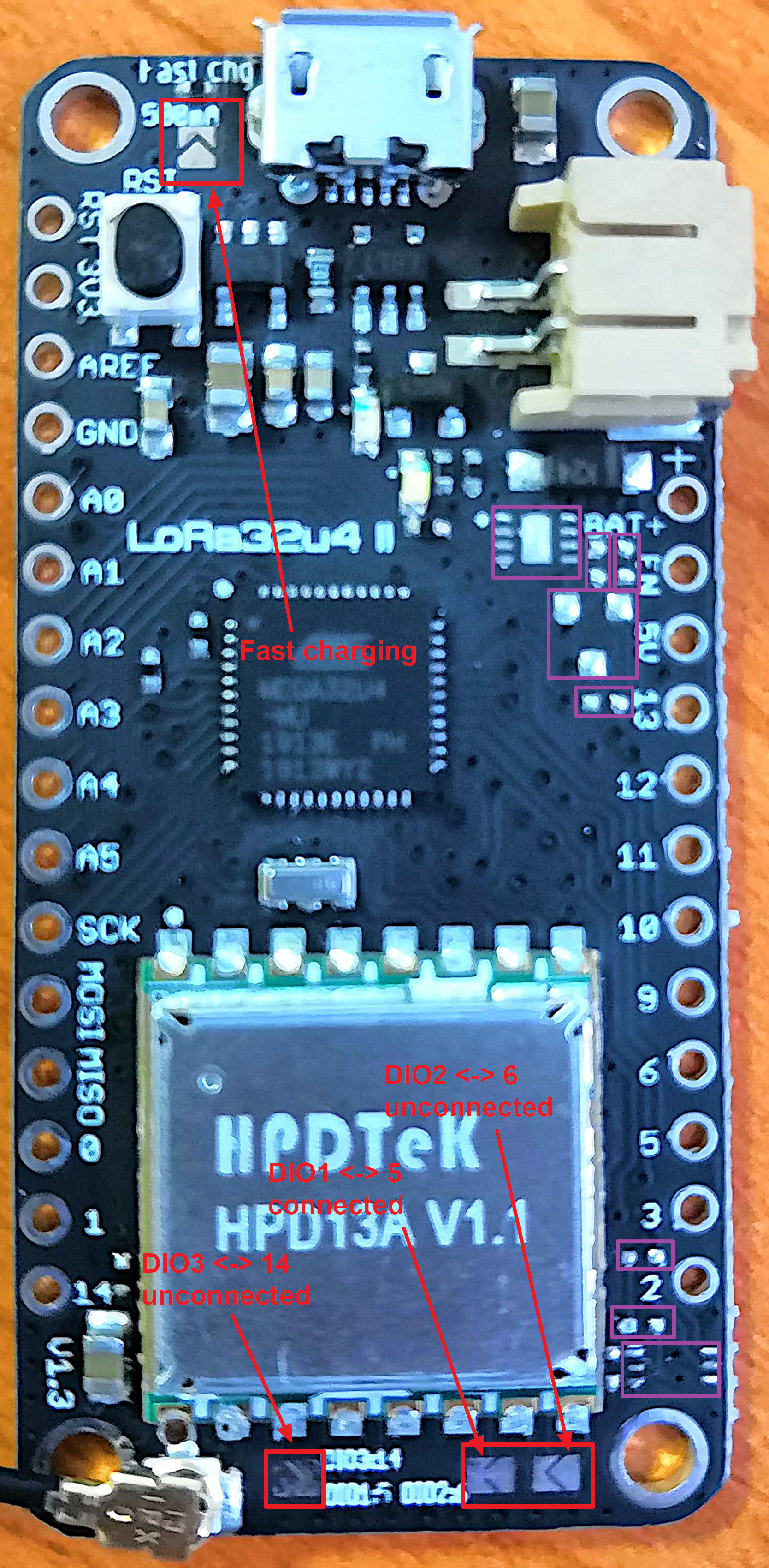
Right-click and select ‘open image in new tab’ to see an image in full resolution.
3 Likes
Great job!
I saw a typo where DIO1 = 6 in your last chapter.
Fixed, thanks.
Hi, thanks, wau - great job you done. Thanks for research. I just made some quict testing - finally my node with Lora board v1.3 is sending packets (data) to TTN with pin mapping
.dio = {/dio0/ 7, /dio1/ 5, /dio2/ LMIC_UNUSED_PIN }
I made no soldering or any board modification at all.
I am still waiting for spec sheet from seller I got it, but no response so far…
Hello ,
I think we won’t have any updated spec sheet from BSFrance before a long, long time. I am working with a LoRa32u4 1.2 and as a French, I was once able to call them (him, because he seems to work alone), after ~15 tries - I assume his mail is just abandoned.
I just wanted to know the values of the resistors in the voltage divider used monitor the battery voltage on the PA1 pin (it looks like the values are different than the ones on the Feather 32u4), and information about the load circuit. I ended up destroying my eyes trying to read the letters on the components.
1 Like
Same for me, as a French, I’ve send a couple of mails a year ago and started to receive detailled answers. Then no more message.
I’ve sent a new mail asking for a v1.3 datasheet, I’ll tell if get something!
I was told 100Kohm +/-5% for v1.2 (+/-1% for “future” v1.3).
v1.3 voltage divider may be controlled by a Mosfet, to avoid being always on.
Thanks a lot for the info ! By the way, isn’t 100Kohm a little too much to make the ADC reading work properly ? (I didn’t tried it yet with the 32u4, but for the LoRa M3-D L151 which I suspect to have the same voltage divider, I couldn’t read properly the ADC values from this pin - values were floating from 3.0 to 4.9V after conversion, and not 4.2V as it supposedly should be). Still investigating.
1 Like
I simply use this code (with one float variable!). I don’t remember having any problem.
#define VBATPIN A9

float measuredvbat = analogRead(VBATPIN);
measuredvbat *= 2;    // we divided by 2, so multiply back
measuredvbat *= 3.3;  // Multiply by 3.3V, our reference voltage
measuredvbat /= 1024; // convert to voltage
Serial.print("VBat: " ); Serial.println(measuredvbat);
My last contact with BSFrance was more than a year ago (about their LoRaM3-D boards). After some good initial contacts, responses suddenly stopped and I haven’t heard from BSFrance since. I also haven’t seen any documentation and Arduino core updates for their LoRaWAN products since.
Short after I was informed (by external source) that he was very busy with a project for a large company and appears to have limited time for his BSFrance activities.
Surprised to see that the new v1.3 version of LoRa32u4 II is available, while documentation (and Arduino core) have still not been updated since v1.1.
Wanted
Who can provide some sharp, well lit photos of LoRa32u4 v1.3 that I can add to the topic start?
(of both sides of the board)