I had not noticed the difference, because I have not (yet) checked/compared it’s memory use.
BTW: as a workaround you may disable PING and BEACONS (see my above platformio.ini) to get more available memory (useful for AVR).
I had not noticed the difference, because I have not (yet) checked/compared it’s memory use.
BTW: as a workaround you may disable PING and BEACONS (see my above platformio.ini) to get more available memory (useful for AVR).
or change the bootloader … saves a few bytes (AVR)
I’m sure it’s the best one 
I noticed size because with ULPNode lib (and some sensors) got warning about RAM usage at compilation, and even does not fit to flash (I have optiboot of course and had disabled PING and BEACONS, I needed to disable debug in my code to be able to fit) and may be that’s what is causing my hazardous reset by lack of RAM, but I had no time to check this so reversed to old one. Also new one add 2 new events that I need to manage.
About the mosfet to drive power for sensor; what about this implementation using TPL chip
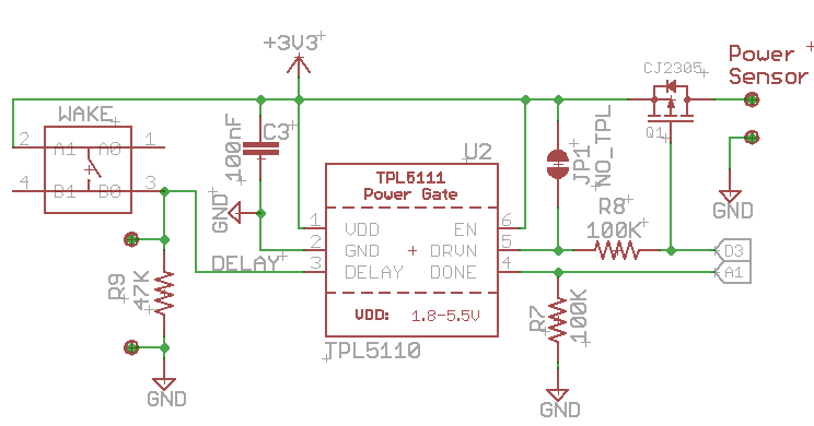
Which one do you prefer? controling mosfet by TPL D3 like this schematic or by another GPIO only like previous post above?
Can you make it selectable via a bridge?
In my use case, I prefer a separate GPIO as I can then keep the power on time shorter, just the time needed to collect data, not the time spent in sending and other housekeeping…
But I can see other use cases where you want to keep it simple and save a GPIO port…
Not sure I see the difference, when you go into sleep mode you need to be sure the logic state of the driving pin is such that the device is off, be that high or low.
If you use low side switching, you can create a situation where your devices are phantom powered through I\O pins.
I think this is what I’m having problems with, why I can’t get my TPL/wakeup to work on my mini-lora v1.2 boards.
(I have so far not been successful with the ULP-node code as a base).
@Amedee, do you have some code to share to show how to do “non hardware IRQ TPL”?
@Basse you can do a dirty hack connect A2 (TPL pin) to A0, A1 or A3) this mean that TPL pin goes to A2 and for example A1 (so let A2 as input)
Then take a look at the sample code wake_buton.ino and add the new IRQ IRQ_SENSOR_A1_ENABLE to wake
  // Light off LEDs, remove power from sensors and RF modules
  ulpn.RGBShow(RGB_OFF);
  ulpn.setDevice(DEVICE_LED_OFF | DEVICE_SENSORS_OFF | DEVICE_RF_OFF);

  // Disable all CPU peripherals for low power
  ulpn.disableCPUDevices();

  // Enable A1 IRQ with pullup (I think both rising and falling will trigger IRQ)
  ulpn.setSensorsIRQ(IRQ_SENSOR_A1_ENABLE , true);

  // go to sleep mode, NO BOD, only push button and A1 can wake us
  ulpn.sleepDeviceWake(SLEEP_BOD_OFF | SLEEP_WAKE_SWITCH, 0);

  // We've been waked up by a IRQ, disable ours until we done the job
  ulpn.setIRQ(IRQ_SWITCH_DISABLE);

  // Disable A1 IRQ
  ulpn.setSensorsIRQ(IRQ_SENSOR_A1_DISABLE);
That should works, don’t forget to add a callback with ulpn.attachSensorInterrupt(your_handler) for sensor IRQ (A1) if you need to detect witch irq waked the node
Use with caution with 1.3 all will change with dedicated TPL Wake pin connected to D3 (INT1), it’s just a dirty workaround
Take a look into the lib setSensorsIRQ() on how to do interrupt with PCCINT register, may be it’s also possible to add A2 in this routine to make things simpler.
If my memory serves well, there is somewhere in this thread a link to a library handling all interrupt types…
Edit: in the MiniLora thread
Correct t’s named as far as I remember PinChangeInterrupt
What an overhead of flash and memory use to drive 1 pin interrupt, when we have onboard LoRaWAN stack and when this INT could be managed only with a few lines of code 
The MCCI licensing is a complete mess…
They decided to re-license their code because upstream IBM did.
While I understand the intend, it is not really legal as by doing this they re-license code which has been contributed under another license agreement. This can only be done if all project contributors agree on this license change…
Hi @Charles,
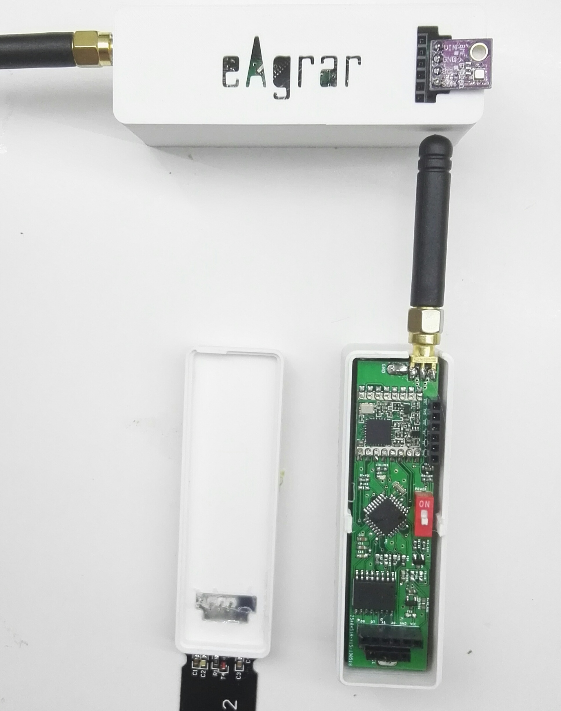
I would like to test your library on my own board. It is based on Arduino Mini Pro, RFM95 and use RTC DS3231 as interrupt. Without voltage regulator I got around 2.5uA in sleep mode. I would like to implement TPL5110 also. So, I would be glad if you can enable me access to your library. 
This is my board
Holidays are almost over… let’s get started 

Hello,
I have a lot of Mini-LoRa boards here now and would like to test the lib and give feedback.
Is it possible to get access to the sources please?
Hi … if you ask Charles that by PM and also show your github to him.
I’d be happy to test too if this is still ongoing. tkerby on github
Is this project still active? I don’t see any action of this topic 
any news on this getting to a publicly available state? i’m planning on putting several BME280 nodes into the wild over the year and it of course would be great to be able to get them as ‘low power’ as possible right from the start.
happily would be trying to get to work what is there already as well - but probably won’t be able to contribute much more than optimizing documentation for lesser experienced users and finding bugs…
cheers,
markus.
It is better to switch the sensor off with HIGH level in the mosfet (P-channel). Because before you go to sleep just have to declare that pin as an INPUT (no pull-up), because of the TTL definition it will be stay in the HIGH level and the sensor will be off.
In TTL, an input floating pin is a HIGH level.