Hi Charles, I think we need to adjust the LMIC ticks so the duty cycle is not violated. Some solution posted in this forum includes adjusting the Timer0 overflow (which then adjust the micros()). But, I think that is too hardware dependent. I’m looking whether we can add a function to LMIC like adjustTime(SLEEP_INTERVAL) (I’m simply putting a name here). Call after the MCU wake up.
@rocketscream
I’m sending a packet every 5 min (approx), so I don’t think I’m violating the duty cyle. In fact, the Watchdog wake me 37 times on which I’m going back to sleep immediately. the 38 wake, I’m powering sensors, do measure, send packet and going to sleep again 
For those asked here a skeleton of my code, I removed lot of debug and sensor management, but you’ve got the main concept. Note that push button help me to do different actions depending on how much time I press it
// Schedule TX every this many seconds (multiple of 8 due to watchdog).
// Takr care of to duty cycle limitations).
#define TX_INTERVAL 300

// Watchdog count between transmit
#define WDT_WAKE_COUNT (TX_INTERVAL/8)

// Some counter demo used in IRQ
volatile uint32_t iWakeCounter = 0;
volatile uint32_t iSwitchCounter = 0 ;
volatile uint32_t iWatchdogCounter = 0 ;
volatile uint8_t  iIrq=0;
bool timeToSleep = false;

// give ULPNode instance
ULPNode  ulpn;

/* ======================================================================
Function: wakeInterruptHandler
Purpose : IRQ Handler called when external device wake us
Input   : -
Output  : -
Comments: once fired this interrupt disable itself
====================================================================== */
void wakeInterruptHandler(void)
{
  // Inc counter and set flag for main loop
  iWakeCounter++;
  iIrq |= SLEEP_WAKE_EXT;
}

/* ======================================================================
Function: switchInterruptHandler
Purpose : IRQ Handler called when switch is pressed/released (for wake)
Input   : -
Output  : -
Comments: once fired this interrupt disable itself
====================================================================== */
void switchInterruptHandler(void)
{
  // Inc counter and set flag for main loop
  iSwitchCounter++;
  iIrq |= SLEEP_WAKE_SWITCH;
}

/* ======================================================================
Function: watchdogInterruptHandler
Purpose : IRQ Handler called when watchdog IRQ occurs
Input   : -
Output  : -
Comments: once fired this interrupt disable the watchdog
====================================================================== */
void watchdogInterruptHandler(void)
{
  // Inc counter and set flag for main loop
  iWatchdogCounter++;
  iIrq |= SLEEP_WAKE_WATCHDOG ;
}


/* ======================================================================
Function: onEvent
Purpose : called my LMIC stack on event received
Input   : event type
Output  : -
Comments: -
====================================================================== */
void onEvent (ev_t ev) {
  static unsigned long last_time=0;
  unsigned long now = millis() / 1000;
  showTime(now);
  DebugF(" ("); showTime(now-last_time);  DebugF(") ");
  last_time = now;
  switch(ev) {
    case EV_SCAN_TIMEOUT:   DebuglnF("EV_SCAN_TIMEOUT");    break;
    case EV_BEACON_FOUND:   DebuglnF("EV_BEACON_FOUND");    break;
    case EV_BEACON_MISSED:  DebuglnF("EV_BEACON_MISSED");   break;
    case EV_BEACON_TRACKED: DebuglnF("EV_BEACON_TRACKED");  break;
    case EV_JOINING:        DebuglnF("EV_JOINING");         break;
    case EV_RFU1:           DebuglnF("EV_RFU1");            break;
    case EV_JOIN_FAILED:    DebuglnF("EV_JOIN_FAILED");     break;
    case EV_REJOIN_FAILED:  DebuglnF("EV_REJOIN_FAILED");   break;
    case EV_LOST_TSYNC:     DebuglnF("EV_LOST_TSYNC");      break;
    case EV_RESET:          DebuglnF("EV_RESET");           break;
    case EV_RXCOMPLETE:     DebuglnF("EV_RXCOMPLETE");      break;
    case EV_LINK_DEAD:      DebuglnF("EV_LINK_DEAD");       break;
    case EV_LINK_ALIVE:     DebuglnF("EV_LINK_ALIVE");      break;
    case EV_SCAN_FOUND:     DebuglnF("EV_SCAN_FOUND");      break;
    case EV_TXSTART:        DebuglnF("EV_TXSTART");         break;

    case EV_TXCOMPLETE:
      DebugF("EV_TXCOMPLETE ");

      // Remove timeout job;
      os_clearCallback(&timeoutjob);

      if (LMIC.txrxFlags & TXRX_ACK) {
        DebugF("with ACK");
        DebugFlush();
        ulpn.RGBBlink(2, RGB_GREEN, WDTO_120MS);
      } else {
        // Needed ACK didn't received it ?
        if ( send_packet_ack) {
          ulpn.RGBBlink(1, RGB_RED, WDTO_120MS);
        }
      }
      Debugln();

      if (LMIC.dataLen) {
        DebugF("Received ");
        Debugln(LMIC.dataLen);
        DebuglnF(" bytes");
        DebugFlush();
        ulpn.RGBBlink(2, RGB_BLUE, WDTO_120MS);
      }

      ulpn.RGBShow(RGB_OFF);
      // we done
      timeToSleep = true;
    break;

    case EV_JOINED: {
      // Disable link check validation (automatically enabled
      // during join, but not supported by TTN at this time).
      LMIC_setLinkCheckMode(0);

      // Ok send our first data in 10 ms
      os_setTimedCallback(&sendjob, os_getTime() + ms2osticks(10), do_send);
    }
    break;

    default:
      DebugF("Unknown event #");
      Debugln(ev);
    break;
    }
  }

/* ======================================================================
Function: do_send
Purpose : send LoraWAN packet
Input   :
Output  : -
Comments: -
====================================================================== */
void do_send(osjob_t* j)
{
  static uint16_t frameCounter=0;

  // Check if there is not a current TX/RX job running
  if (LMIC.opmode & OP_TXRXPEND) {
    #if DEBUG > 1
    showTime(millis() / 1000);
    DebuglnF(" OP_TXRXPEND, not sending");
    #endif

  } else if (LMIC.opmode & OP_JOINING) {
    #if DEBUG > 1
    showTime(millis() / 1000);
    DebuglnF(" OP_JOINING, not sending");
    #endif
  } else {
    uint8_t len = 0;
    uint8_t payload[32] ; // Max, not all will be used, len is calculated on each data added
    uint8_t *p=&payload[0];

    // sensors reading + payload creation
    // ...
    // ...

    ulpn.setDevice(DEVICE_SENSORS_OFF);

    // calculate Len of packet we created
    len = p - &payload[0];

    // Send Data
    LMIC_setTxData2(1, payload, len,  send_packet_ack);

  }
}


/* ======================================================================
Function: setup
Purpose : setup initial config
Input   :
Output  : -
Comments: -
====================================================================== */
void setup() {
  uint8_t tmp;

  // Init ULPNode I/O, Radio; Vbat
  ulpn.init();

  // Enable global watchdog to avoid lockups
  ulpn.setWatchdog(APP_WATCHDOG_TO);

  ulpn.RGBShow(RGB_OFF);

  // Define IRQ callbacks we need in "user space"
  // Here we want callbacks of
  // watchdog, wake and switch push button
  ulpn.attachWakeInterrupt( wakeInterruptHandler );
  ulpn.attachSwitchInterrupt( switchInterruptHandler );
  ulpn.attachWatchdogInterrupt( watchdogInterruptHandler );

  // Give power to sensors
  ulpn.setDevice(DEVICE_SENSORS_ON);

  SERIAL_DEBUG.begin(SERIAL_PORT_SPEED);

  // Do a I2C scan, this will look for known devices and
  // set the accordings flags to global status
  // You can use it for debug
  if ( (tmp=ulpn.i2cScan()) > 0 ) {
    ulpn.RGBBlink(tmp, RGB_PINK, WDTO_120MS);
  }

  os_getBattLevel();

  // LMIC init
  os_init();

  // Reset the MAC state. Session and pending data transfers will be discarded.
  LMIC_reset();

  // Enable data rate adaptation
  LMIC_setAdrMode(1);

  // Increase RX1 Windows by 1% in case of clock error on board (crystal shift)
  // This clearly increase son OTAA Join request to works first time even with SF7
  LMIC_setClockError(MAX_CLOCK_ERROR * 1 / 100);

  // Join the network, sending will be
  // started after the event "Joined"
  LMIC_startJoining();

  timeToSleep = false;
}


/* ======================================================================
Function: loop
Purpose : main loop
Input   : -
Output  : -
Comments: -
====================================================================== */
void loop() {

  static uint8_t wdt_period = APP_WATCHDOG_8S;// in 8S (set to APP_WATCHDOG_NONE for external wake only)
  static uint8_t wdt_count  = WDT_WAKE_COUNT; // number of WDT wake between transmit

  static bool led_state ;
  bool new_led_state ;
  int16_t send_packet_ms = 0; // Delay sending packet in xxx ms

  uint32_t WakeCounter = 0;
  uint32_t SwitchCounter = 0 ;
  uint32_t WatchdogCounter = 0;
  uint8_t  IrqTrigger = 0;

  // action to be done with button, default none
  btn_action_e SwitchAction = BTN_NONE;

  // Need to go sleeping ?
  if (timeToSleep) {

    // Wait n WDT wake to do things
    while (wdt_count--) {

      goSleeping( SLEEP_BOD_OFF | SLEEP_WAKE_EXT | SLEEP_WAKE_SWITCH, wdt_period );

      // IRQ are disabled, it's safe to get these values
      WakeCounter     = iWakeCounter;
      SwitchCounter   = iSwitchCounter;
      WatchdogCounter = iWatchdogCounter;
      IrqTrigger      = iIrq;

      // Only Watchdog
      if (IrqTrigger == SLEEP_WAKE_WATCHDOG && wdt_count) {
        // Ack this IRQ
        IrqTrigger &= ~SLEEP_WAKE_WATCHDOG;

      } else {
        // Break of while exit sleep mode if it's other IRQ
        wdt_count =0;
      }
    }

    // Restart out watchdog count counter
    wdt_count = WDT_WAKE_COUNT;

    // Set to true for next loop
    // will be reset in case ne need to transmit
    timeToSleep = true;
  }

  // Enable global watchdog to avoid lockups
  ulpn.setWatchdog(APP_WATCHDOG_TO);

  // Ok loop in case we've been triggered by differents IRQ
  // we need to proccess all IRQ
  // I don't think this could happen, but does not hurt to check
  while (IrqTrigger)  {
    // Reset RGB default color to none
    ulpn.RGBSetColor(RGB_OFF);

    // Waked by external Wake
    if (IrqTrigger & SLEEP_WAKE_EXT ) {
      // Ack this IRQ
      IrqTrigger &= ~SLEEP_WAKE_EXT;

      ulpn.RGBShow(RGB_PINK);

      // Need to send a packet in 100 ms
      send_packet_ms = 100;

    // Waked by push button
    } else if (IrqTrigger & SLEEP_WAKE_SWITCH ) {

      // Get switch port state
      uint8_t button_port = digitalRead(SWITCH_PIN);

      // Ack this IRQ
      IrqTrigger &= ~SLEEP_WAKE_SWITCH;

      // Button pressed
      if (button_port==BTN_PRESSED) {
        btn_state_e btn_state;

        // we enter into the loop to manage
        // the function that will be done
        // depending on button press duration
        do {
          // keep watching the push button:
          btn_state = ulpn.buttonManageState(button_port);

          if (btn_state == BTN_WAIT_LONG_RELEASE)
            ulpn.setDevice(DEVICE_LED_OFF);

          // read new state button
          button_port = digitalRead(SWITCH_PIN);

          // Pat the dog, this loop can be as long
          // as button is pressed
          wdt_reset();
        }
        // we loop until button state machine finished
        while (btn_state != BTN_WAIT_PUSH);

        // Get and save action we need to do after button analyze
        SwitchAction = ulpn.buttonAction();

      // If button still pressed
      }

    } else if (IrqTrigger & SLEEP_WAKE_WATCHDOG ) {
      // Waked by watchdog
      // Ack this IRQ
      IrqTrigger &= ~SLEEP_WAKE_WATCHDOG;

      // Need to send a packet in 100 ms
      send_packet_ms = 100;

    } else if ( IrqTrigger ) {
      // Another Wake ? weird !!!

      // ACK all other parasite IRQ, except the one we're dealing on
      IrqTrigger &= ( SLEEP_WAKE_SWITCH | SLEEP_WAKE_WATCHDOG ) ;
    }

   // On button timeout we do absolutely nothing
    if ( SwitchAction != BTN_TIMEOUT) {

      // What action we want to do depending on button press ?
      if (SwitchAction != BTN_NONE ) {

        if (SwitchAction==BTN_BAD_PRESS) {
        }
        if (SwitchAction==BTN_QUICK_PRESS) {
          // Will send a packet
          send_packet_ms = 10;
        }
        // Button pressed between 1 and 2 seconds
        if (SwitchAction==BTN_PRESSED_12) {

          // Invert ACK Mode
          if (send_packet_ack) {
            send_packet_ack = false;
            ulpn.RGBBlink(2, RGB_RED, WDTO_120MS);
          } else {
            send_packet_ack = true;
            ulpn.RGBBlink(2, RGB_GREEN, WDTO_120MS);
          }
        }
        // Button pressed between 2 and 3 seconds ?
        if ( SwitchAction==BTN_PRESSED_23) {
          // disable watchdog wake (now only external interrupts
          wdt_period = APP_WATCHDOG_NONE;
        }
        if (SwitchAction==BTN_PRESSED_34) {
          // enable watchdog wake
          wdt_period = APP_WATCHDOG_8S;
        }
        if (SwitchAction==BTN_PRESSED_45) {
        }
        if (SwitchAction==BTN_TIMEOUT) {
        }

      } // we had a button press

    } // if not button time out

    // Pat the dog
    wdt_reset();

  } // While IrqTrigger

  // something to send
  if (send_packet_ms) {
    timeToSleep = false;
    os_setTimedCallback(&sendjob, os_getTime()+ ms2osticks(send_packet_ms), do_send);
    send_packet_ms = 0;
  }

  // We've done all our IRQ, ACK them !!!
  cli();
  iIrq = 0;
  sei();

  // Pat the dog
  wdt_reset();

  // Don't forget LMIC STACK
  os_runloop_once();

  // All follow is Led management

  // Let join at the begining of if sequence,
  // is prior to send because joining state send data
  // Joining Quick blink 50ms on each 1/5 second
  if ( LMIC.opmode & (OP_JOINING | OP_REJOIN) )  {
    //new_led_state = ((millis() % 200) < 50) ? HIGH : LOW;
    new_led_state = ((millis() % 150) < 10) ? HIGH : LOW;

    // If sensors detected
    if (ulpn.status() & ( RF_NODE_STATE_SENSOR) ) {
      // Join deal with GREEN
      ulpn.RGBSetColor(RGB_GREEN);
    } else {
      // Join deal with RED
      ulpn.RGBSetColor(RGB_RED);
    }

  }

  // Small blink 100ms on each 1/2sec
  if (LMIC.opmode & (OP_TXDATA | OP_TXRXPEND)) {
    // Sending and not joining else keep join speed
    if ( !(LMIC.opmode & (OP_JOINING | OP_REJOIN)) )  {
      new_led_state = ((millis() % 500) < 10) ? HIGH : LOW;
    }

    // If sensors detected
    if (ulpn.status() & ( RF_NODE_STATE_SENSOR) ) {
      // Send deal with BLUE + GREEN
      ulpn.RGBSetColor(RGB_CYAN);
    } else {
      // Send deal with BLUE + RED
      ulpn.RGBSetColor(RGB_PINK);
    }

  }

  // This should not happen but blink yellow to see
  if ( LMIC.opmode & (OP_TXDATA | OP_TXRXPEND | OP_JOINING | OP_REJOIN) == 0 ) {
    new_led_state = ((millis() % 2000) < 200) ? HIGH : LOW;

    // Other all is off RED + GREEN
    ulpn.RGBSetColor(RGB_YELLOW);
  }

  // led  need to change state ?
  // avoid digitalWrite() for nothing
  if (led_state != new_led_state) {
    if (new_led_state == HIGH) {
      ulpn.RGBShow();
    } else {
      ulpn.RGBShow(RGB_OFF);
    }

    led_state = new_led_state;

  }
}
7 Likes
@Charles
I would like to thank you for sharing your works and your ideas. There is so much to learn.
I was wondering what the purpose of using the Microchip 24AA02E64T ? I don’t get it. If someone can explain, It will be kind.
@Under5hadow
Thanks for your comment. The Chip is to have a unique LoraWan ID but it’s not mandatory to have this chip, you can set your ID in your sketch code, no problem.
1 Like
Oh Ok. Sorry for my weakness on electronics. I’m a newbie there ^^
How isthe microchip programmed ? Through the arduino ?
No problem, forums are here for this
Microchip ID is factory programmed but as it’s an I2C EEP also (as far as I know) you should be able to put some data onto, but the main code goes into the arduino mini with code flashed with Arduino IDE.
And as the arduino pro mini also have a EEP, you don’t need to use the Microchip one. Just in case you want to be sure to have a unique factory ID for your device.
So to be simple, if you’re not sure what to do with Microchip 24AA02E64T, you just don’t need to have it, keep only the Arduino Pro Mini and put your device ID in your sketch with APPEUI and APPKEY
3 Likes
The big problem I see is even if you buy these chips, someone may have used the same ID by randomly generating one.
It would be great if TTN could generate a set of device IDs for an application and export them so you can customise into EEPROM on the bench
I’m not a huge specialist, may be TTN guys will correct me, but I think if it’s not on the same APPEUI, same devices ID are not a problem? but may be I’m wrong?
These IDs should be unique, ranges are sold by IEEE, so someone might be generating random IDs, but that would not be a legal solution.
thanks @kersing, always interesting answers you give
So having 2 identicals ID is more a legal problem then a technical problem on the backend?
So this mean all LoRaWan devices sellers may buy range from IEEE or chip with ID.
Not sure everyone is doing this, for now I will do and buy some ID chip even for POC with customers
1 Like
When ttn is used to generate node IDs are these unique and part of an authorised allocation?
@Charles, I just received a batch of the V1.1 PCB’s from PCB’s IO. They look good as always, but taking a closer look at them I find that A4 and A5 don’t seem to connect to the SDA / SCL lines. Taking a closer look at the PCB’s IO project page now there is a V1.1A version which does have the wire-ing correct. I presume that that the 2 missing wires are a bug in the V1.1? 
Luckily nothing 2 wire-wrap wires can’t fix. 
@lex_ph2lb
thanks for your comment, you’re are correct, it’s a bug in v1.1 fixed in V1.1a (PCBs.io and github were updated according to)
I missed that one because tested with Arduino Mini where SCL/SDA are located on 2 other pins (these 2 others are correctly connected)
Source on github,
https://github.com/hallard/Mini-LoRa/issues/1
1 Like
Thanks for the feedback @Charles. Mistakes are easily made with all those different versions of the Arduino’s and clones. 2 small wire-wrap wires will fix the it for my arduino’s. 
@Charles I was wondering If I can use an arduino mega to change the bootlader on my pro mini.
If I understood correctly the process:
- Change bootlader to an custom optiboot
- Build my own ULPN libray (cause yours is under NDA)
- Add any necessary lib for the purpose
Is it Right ?
@Under5hadow
Yeah it could be possible to do with another Arduino following this tutorial.
https://learn.sparkfun.com/tutorials/installing-an-arduino-bootloader
But once again it’s not mandatory, just to get more flash size and easy upload speed higher than 57600
Ok thanks Charles for the tutorial. I already tried their instructions but I got an error when I tried to burn your bootloader.
Just wondering, If the bootlader can be change with another arduino why use a custom ICSP/FTDI programmer ?
I had some problems with your images too as I had to set them up as custom boards in Arduino and I think something on my end wasn’t right.
Instead, I’ve installed Minicore - all the serial setup works, it’s running Optiboot and integrates with the IDE. It also supports the new optimisation methods during linking and you can select the BOD level - see https://github.com/MCUdude/MiniCore
@tkerby
What image are you talking about? The bootloader files located here?
I use MiniCore also, I even asked the author to add new uart speed in #18 because compiling bootloader can be painfull. But I needed to do it on my own, so that’s why I compiled mine and published them for others.
But you’re right, I did not mention how to flash sketch from Arduino IDE once bootloader is installed. Shame on me, it’s because I already have boards defined with correct UART speed on my Arduino IDE (with ULPNode) so I forgot this step.
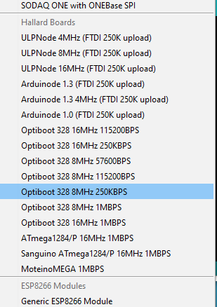
I need to package back my boards file but in the meantime adding this to your boards.txt of your Arduino IDE should bring you all necessary menu entries (quick and dirty fix, I know)
menu.cpu=Processor

##############################################################
#                Optiboot 16Mhz 115200 BOD 1.8V              #
# bootloader of this board is just UNO running up 115200BPS  #
##############################################################
Optiboot16115.name=Optiboot 328 16MHz 115200BPS

Optiboot16115.build.f_cpu=16000000L
Optiboot16115.upload.speed=115200
Optiboot16115.bootloader.file=optiboot_atmega328_1152200_16MHz.hex

Optiboot16115.upload.tool=arduino:avrdude
Optiboot16115.upload.protocol=arduino
Optiboot16115.upload.maximum_size=32256
Optiboot16115.upload.maximum_data_size=2048

Optiboot16115.bootloader.low_fuses=0xff
Optiboot16115.bootloader.high_fuses=0xde
Optiboot16115.bootloader.extended_fuses=0x06
Optiboot16115.bootloader.path=optiboot
Optiboot16115.bootloader.unlock_bits=0x3F
Optiboot16115.bootloader.lock_bits=0xCF
Optiboot16115.bootloader.tool=arduino:avrdude

Optiboot16115.build.mcu=atmega328p
Optiboot16115.build.board=AVR_PRO
Optiboot16115.build.core=arduino:arduino
Optiboot16115.build.variant=arduino:standard

##############################################################
#               Optiboot 16Mhz 250000 BOD 1.8V               #
# bootloader of this board is just UNO running up 250000KBps #
##############################################################
Optiboot16250.name=Optiboot 328 16MHz 250KBPS

Optiboot16250.build.f_cpu=16000000L
Optiboot16250.upload.speed=250000
Optiboot16250.bootloader.file=optiboot_atmega328_250000_16MHz.hex

Optiboot16250.upload.tool=arduino:avrdude
Optiboot16250.upload.protocol=arduino
Optiboot16250.upload.maximum_size=32256
Optiboot16250.upload.maximum_data_size=2048

Optiboot16250.bootloader.low_fuses=0xff
Optiboot16250.bootloader.high_fuses=0xde
Optiboot16250.bootloader.extended_fuses=0x06
Optiboot16250.bootloader.path=optiboot
Optiboot16250.bootloader.unlock_bits=0x3F
Optiboot16250.bootloader.lock_bits=0xCF
Optiboot16250.bootloader.tool=arduino:avrdude

Optiboot16250.build.mcu=atmega328p
Optiboot16250.build.board=AVR_PRO
Optiboot16250.build.core=arduino:arduino
Optiboot16250.build.variant=arduino:standard

##############################################################
#                 Optiboot 8Mhz 57600 BOD 1.8V               #
# bootloader of this board is just UNO running up 57600BPS  #
##############################################################
Optiboot8576.name=Optiboot 328 8MHz 57600BPS

Optiboot8576.build.f_cpu=8000000L
Optiboot8576.upload.speed=57600
Optiboot8576.bootloader.file=optiboot_atmega328_57600_8MHz.hex

Optiboot8576.upload.tool=arduino:avrdude
Optiboot8576.upload.protocol=arduino
Optiboot8576.upload.maximum_size=32256
Optiboot8576.upload.maximum_data_size=2048

Optiboot8576.bootloader.low_fuses=0xff
Optiboot8576.bootloader.high_fuses=0xde
Optiboot8576.bootloader.extended_fuses=0x06
Optiboot8576.bootloader.path=optiboot
Optiboot8576.bootloader.unlock_bits=0x3F
Optiboot8576.bootloader.lock_bits=0xCF
Optiboot8576.bootloader.tool=arduino:avrdude

Optiboot8576.build.mcu=atmega328p
Optiboot8576.build.board=AVR_PRO
Optiboot8576.build.core=arduino:arduino
Optiboot8576.build.variant=arduino:standard


##############################################################
#                Optiboot 8Mhz 115200 BOD 1.8V               #
# bootloader of this board is just UNO running up 250000KBps #
##############################################################
Optiboot8115.name=Optiboot 328 8MHz 115200BPS

Optiboot8115.build.f_cpu=8000000L
Optiboot8115.upload.speed=115200
Optiboot8115.bootloader.file=optiboot_atmega328_1152200_8MHz.hex

Optiboot8115.upload.tool=arduino:avrdude
Optiboot8115.upload.protocol=arduino
Optiboot8115.upload.maximum_size=32256
Optiboot8115.upload.maximum_data_size=2048

Optiboot8115.bootloader.low_fuses=0xff
Optiboot8115.bootloader.high_fuses=0xde
Optiboot8115.bootloader.extended_fuses=0x06
Optiboot8115.bootloader.path=optiboot
Optiboot8115.bootloader.unlock_bits=0x3F
Optiboot8115.bootloader.lock_bits=0xCF
Optiboot8115.bootloader.tool=arduino:avrdude

Optiboot8115.build.mcu=atmega328p
Optiboot8115.build.board=AVR_PRO
Optiboot8115.build.core=arduino:arduino
Optiboot8115.build.variant=arduino:standard


##############################################################
#                Optiboot 8Mhz 250000 BOD 1.8V               #
# bootloader of this board is just UNO running up 250000KBps #
##############################################################
Optiboot8250.name=Optiboot 328 8MHz 250KBPS

Optiboot8250.build.f_cpu=8000000L
Optiboot8250.upload.speed=250000
Optiboot8250.bootloader.file=optiboot_flash_atmega328p_250000_8000000L.hex

Optiboot8250.upload.tool=arduino:avrdude
Optiboot8250.upload.protocol=arduino
Optiboot8250.upload.maximum_size=32256
Optiboot8250.upload.maximum_data_size=2048

Optiboot8250.bootloader.low_fuses=0xff
Optiboot8250.bootloader.high_fuses=0xde
Optiboot8250.bootloader.extended_fuses=0x06
Optiboot8250.bootloader.path=optiboot
Optiboot8250.bootloader.unlock_bits=0x3F
Optiboot8250.bootloader.lock_bits=0xCF
Optiboot8250.bootloader.tool=arduino:avrdude

Optiboot8250.build.mcu=atmega328p
Optiboot8250.build.board=AVR_PRO
Optiboot8250.build.core=arduino:arduino
Optiboot8250.build.variant=arduino:standard

##############################################################
#                Optiboot 8Mhz 1000000 BOD 1.8V              #
#   bootloader of this board is just UNO running up 1MBPS    #
##############################################################
Optiboot81000.name=Optiboot 328 8MHz 1MBPS

Optiboot81000.build.f_cpu=8000000L
Optiboot81000.upload.speed=1000000
Optiboot81000.bootloader.file=optiboot_flash_atmega328p_1000000_8000000L.hex

Optiboot81000.upload.tool=arduino:avrdude
Optiboot81000.upload.protocol=arduino
Optiboot81000.upload.maximum_size=32256
Optiboot81000.upload.maximum_data_size=2048

Optiboot81000.bootloader.low_fuses=0xff
Optiboot81000.bootloader.high_fuses=0xde
Optiboot81000.bootloader.extended_fuses=0x06
Optiboot81000.bootloader.path=optiboot
Optiboot81000.bootloader.unlock_bits=0x3F
Optiboot81000.bootloader.lock_bits=0xCF
Optiboot81000.bootloader.tool=arduino:avrdude

Optiboot81000.build.mcu=atmega328p
Optiboot81000.build.board=AVR_PRO
Optiboot81000.build.core=arduino:arduino
Optiboot81000.build.variant=arduino:standard

##############################################################
#               Optiboot 16Mhz 1000000 BOD 1.8V              #
#   bootloader of this board is just UNO running up 1MBPS    #
##############################################################
Optiboot161000.name=Optiboot 328 16MHz 1MBPS

Optiboot161000.build.f_cpu=16000000L
Optiboot161000.upload.speed=1000000
Optiboot161000.bootloader.file=optiboot_atmega328_1000000_16MHz.hex

Optiboot161000.upload.tool=arduino:avrdude
Optiboot161000.upload.protocol=arduino
Optiboot161000.upload.maximum_size=32256
Optiboot161000.upload.maximum_data_size=2048

Optiboot161000.bootloader.low_fuses=0xff
Optiboot161000.bootloader.high_fuses=0xde
Optiboot161000.bootloader.extended_fuses=0x06
Optiboot161000.bootloader.path=optiboot
Optiboot161000.bootloader.unlock_bits=0x3F
Optiboot161000.bootloader.lock_bits=0xCF
Optiboot161000.bootloader.tool=arduino:avrdude

Optiboot161000.build.mcu=atmega328p
Optiboot161000.build.board=AVR_PRO
Optiboot161000.build.core=arduino:arduino
Optiboot161000.build.variant=arduino:standard


##############################################################
#               Optiboot 16Mhz 1000000 BOD 1.8V              #
#        bootloader for  ATMega1284p running up 1MBPS        #
##############################################################

atmega1284p_1M.name=ATmega1284/P 16MHz 1MBPS

atmega1284p_1M.build.f_cpu=16000000L
atmega1284p_1M.upload.speed=1000000
atmega1284p_1M.bootloader.file=optiboot_atmega1284p_1Mbps_D15.hex

atmega1284p_1M.upload.tool=arduino:avrdude
atmega1284p_1M.upload.protocol=arduino
atmega1284p_1M.upload.maximum_size=130048
atmega1284p_1M.upload.maximum_data_size=16384

atmega1284p_1M.bootloader.low_fuses=0xFF
atmega1284p_1M.bootloader.high_fuses=0xDE
atmega1284p_1M.bootloader.extended_fuses=0xFE
atmega1284p_1M.bootloader.path=optiboot
atmega1284p_1M.bootloader.unlock_bits=0x3F
atmega1284p_1M.bootloader.lock_bits=0x0F
atmega1284p_1M.bootloader.tool=arduino:avrdude

atmega1284p_1M.build.mcu=atmega1284p
atmega1284p_1M.build.board=AVR_MOTEINOMEGA
atmega1284p_1M.build.core=arduino:arduino
atmega1284p_1M.build.variant=MoteinoMEGA
1 Like