Generic Node join-request / join-accept loop during sensors_loawan demo

I recently received 2 GNSE’s in the US and have been trying to get them connected to the LoRa Network. I have created a test app on the things stack and claimed the nodes.

The node model and frequency can be found below.
Model: v1.1b
Frequency: EU868

I have confirmed functionality of all the sensors using the basic demo program and have moved on to configuring the nodes to connect to the LoRa Network.

After updating the APPEUI, DEVEUI, and APPKEY in the app_conf.h file, I have started seeing a “Accept join-request” and “Forward join-accept message” messages on the console end when the device successfully joins via OTAA. Typically this pair of messages occurs multiple times within a few minutes of the successful connection via OTAA. On the device side, after OTAA, RX_1 and RX_2 consistently time out and no data is successfully transmitted from the GNSE to the console.

I’m not quite sure how to proceed as it appear the device is successfully communicating with the nearest gateway but then failing to successfully maintain the connection/transmit any of the relevant data.
Screenshot 2023-03-06 181903

RX1 and RX2 are supposed to time out. The device log shows it joined successfully and is sending uplinks. Looking at the tx frequencies after the join makes me thing there is an error in the device setup somewhere as those frequencies do not match the TTN values provided here.
That explains why you aren’t seeing any data at TTN because there will not be a gateway listening at the frequencies the device uses.
Did you select the right frequency plan while setting up the device? ( band 2 marked used by TTN )

On the console end, I have the frequency plan set to “United States 902-928 MHz, FSB 2 (used by TTN)”.

On the device end, I believe the only modifications I made regarding frequency was changing the region to US915 from the default EU option.

Is there another parameter that needs to be modified here to specify FSB 2?

Looks like device is not receiving the Join-Accept messages from the GW.
Unfortunately, I don’t have a US gateway at hand to replicate this.
@adrianmares could you please take a look at this when you get a chance?

I disagree. In the screendump (why not text so we can quote it @mcvoltaic) it states" JOINED = OTAA (between 16s436 and 20s958)
After that point it starts using frequencies that are outside the TTN range for TX.
20s958: 905.7MHz
30s968: 908.3MHz
40s978: 905.3MHz ← Matches TTN plan
50s988: 905.5MHz

@mcvoltaic : you are sending every 10 seconds which far too frequently for the TTN FUP. Please make sure you do not violate the FUP. (30 seconds uplink time a day)

@cndrxn I am not very familiar with the settings for US915 in the node stack, is there a setting to limit the node to one subband in stead of using all 64 channels?

1 Like

It’s based on LoRaMAC-node, and while there are some hacks to select the mask there, I wouldn’t recommend it.

I think that what happens is that the device joins at a very low data rate, and because of this the Join Accept does not contain a CFList (since the downlink DR needs to match the uplink DR) that would tell it to use FSB2.
This means that the end device still has all 72 channels enabled and probably cycles through them, until an uplink is received that would contain a LinkADRReq command that would make it use FSB2.

My recommendation is to increase the data rate index used for join requests, in order to allow the end device to actually receive the CFList whilst joining.

2 Likes

As a general rule one should not modify the files under mac directory of LoRaMac-node project.

As @adrianmares mentioned it is not recommended to limit the channels usage for the Join procedure. In addition by doing so the end-device is no more LoRaWAN certifiable.
An end-device operating in bands like AU915 and US915 must be able to use all 64+8 channels.

The problem that we encounter is that 64+8 channels gateways are quite expensive and only a few network operators are able to invest and deploy them.

As most people can only afford to buy 8 channels gateways or maybe 16 channels gateways the network operators such TTN decided to select one of the available 8 blocks.

Therefore some compromises must be accepted because of the use of 8 channels gateways.
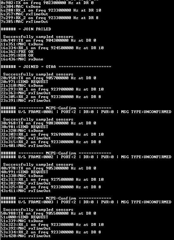
The biggest compromise that we must accept is that more than one JoinReq attempt maybe necessary before the JoinAccept is transmitted/received.

To speed up the Join procedure the LoRaWAN Regional Parameters specification provides an algorithm description for such task.
image

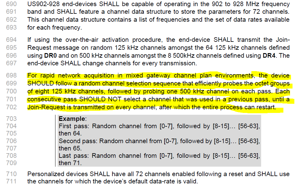
LoRaMac-node project implements the recommended algorithm. This means that when an end-device tries to connect to TTN at minimum 2 JoinReq uplinks will be transmitted before the network is able to send the JoinAccept.

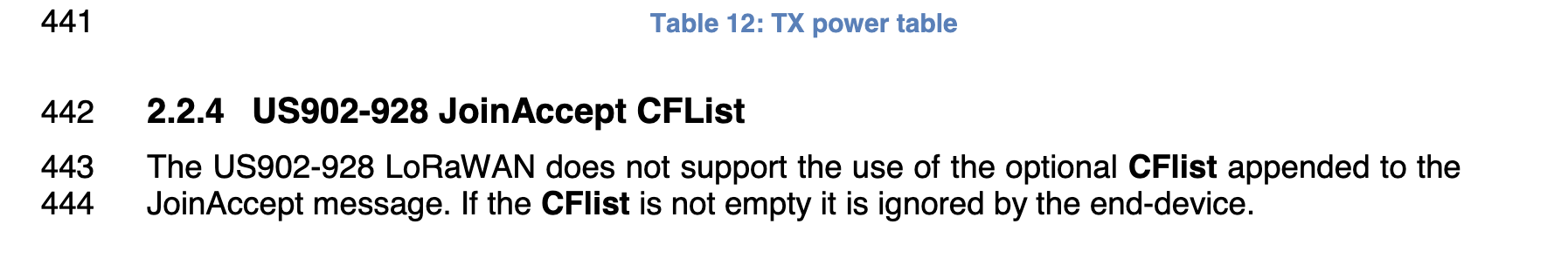
Concerning the CFList.
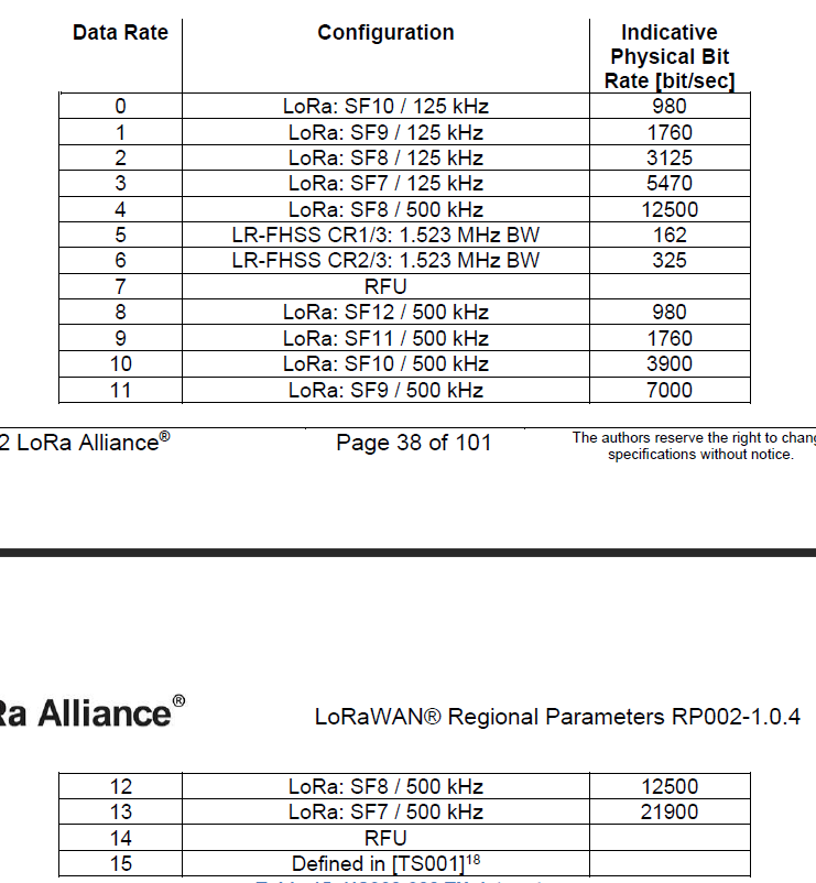
As it can be observed in previous specification excerpt the end-devices must use either DR0 or DR4 to send JoinReq uplinks in order to be LoRaWAN compliant.
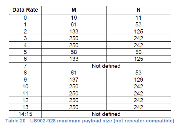
This means that the network server should be able to send the CFList within the JoinAccept message. In US915 region the downlink data rates use 500 kHz bandwidth. According to FCC rules there are no restrictions on payload sizes as the dwell-time limitations do not apply.
FCC dwell-time limitation only applies for 125 kHz bandwidth data rates (uplinks).

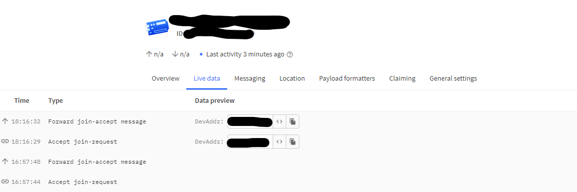
To solve the original issue what we need to know is why the end-device did not receive the CFList or if received why it did not applied it.
The provided logs do not allow to know if the network has really sent the CFList and if it has sent we don’t know if its contents is correct.
Some debugging steps must be done in order to know the origin of the issue.

With LoRaMac-node if one really needs to limit the number of channels it is best to use the stack provided APIs to perform such changes.

Example on how to limit the channels to the 1st block of 8:

/**
 * Main application entry point.
 */
int main( void )
{
    ...
                mibReq.Type = MIB_PUBLIC_NETWORK;
                mibReq.Param.EnablePublicNetwork = LORAWAN_PUBLIC_NETWORK;
                LoRaMacMibSetRequestConfirm( &mibReq );

                mibReq.Type = MIB_ADR;
                mibReq.Param.AdrEnable = LORAWAN_ADR_ON;
                LoRaMacMibSetRequestConfirm( &mibReq );

#if defined( REGION_EU868 ) || defined( REGION_RU864 ) || defined( REGION_CN779 ) || defined( REGION_EU433 )
                LoRaMacTestSetDutyCycleOn( LORAWAN_DUTYCYCLE_ON );
#endif
                mibReq.Type = MIB_SYSTEM_MAX_RX_ERROR;
                mibReq.Param.SystemMaxRxError = 20;
                LoRaMacMibSetRequestConfirm( &mibReq );

#if defined( REGION_AU915 ) || defined( REGION_US915 )
                // Enabling 1st block of 8 channels (0-7) + channel 64
                uint16_t channelMask[] = { 0x00FF, 0x0000, 0x0000, 0x0000, 0x0001, 0x0000};
                mibReq.Type = MIB_CHANNELS_MASK;
                mibReq.Param.ChannelsMask = channelMask;
                LoRaMacMibSetRequestConfirm( &mibReq );
                mibReq.Type = MIB_CHANNELS_DEFAULT_MASK;
                mibReq.Param.ChannelsDefaultMask = channelMask;
                LoRaMacMibSetRequestConfirm( &mibReq );
#endif
                LoRaMacStart( );

                mibReq.Type = MIB_NETWORK_ACTIVATION;
                status = LoRaMacMibGetRequestConfirm( &mibReq );
    ...
}

Therefore to enable the 2nd block of 8+1 channels one needs to change
uint16_t channelMask[] = { 0x00FF, 0x0000, 0x0000, 0x0000, 0x0001, 0x0000};
To:
uint16_t channelMask[] = { 0xFF00, 0x0000, 0x0000, 0x0000, 0x0002, 0x0000}; // Enabling 2nd block of 8 channels (8-15) + channel 65

2 Likes

Because the DR was too low to allow a CFList to be included in the Join Accept, so it was then pending receiving a LinkADRReq downlink which would require it to hit a channel for its uplink in use for the gateway/LNS being used.

Excellent, just off to de-hack a couple of projects and implement this! :roll_eyes:

As I tried to explain the CFList can be sent for a JoinReqest sent using DR0.

In US915 region the uplink and downlink data rates are different. when the uplink is sent with DR0 the downlinks are send with DR8 on Rx1 window and Rx2 window also uses DR8.

A JoinAccept with CFList has a total payload size of 32 bytes. As you can observe from the specification DR8 has a maximum payload size of 61 bytes. Therefore the CFList can be transmitted when using DR0 for the JoinRequest uplink.

image

image

In addition this is something that is verified when going trough LoRaWAN certification process for the end-device.

2 Likes

Ah, OK, understand, the asymmetrical plans are a real brain twister, and I should have remembered from debugging the Lacuna setup for US915 but I’ve slept since.

So as well as looking at the channel plan changes, I’ll revisit a project that may have been impacted in that regard!

Perhaps @adrianmares can advise if the TTI stack is being overly cautious with its downlinks.

1 Like

Thank you for the intervention, @mluis1. You are right that the CFList should indeed fit into both receive windows, and that using different data rate indices is not compliant.

I dug dipper into why the CFList is missing and the response is that in RP1-1.0.2revB the CFList actually is not specified for US915:

I think that the end devices mentioned here are registered as RP1-1.0.2revB devices and this is why the Network Server is not including a CFList. I think also the end device itself is certified as a RP1-1.0.2revB device.

With that being said, the version of LoRaMAC-node on which the GN is based is 4.4.4, which should support LoRaWAN 1.0.3 and RP1-1.0.3a, which would include the CFList. In my tests, when I moved it to LoRaWAN 1.0.3 I got a CFList and I did not require additional channel mask changes after the Join Accept.

3 Likes

@adrianmares Good catch. I was supposing that LoRaWAN 1.0.4 was the target specification.

The LoRaMac-node v4.4.4 is indeed implementing LoRaWAN 1.0.3 + RP1-1.0.3a which supports the CFList.

Some background about all these versions issues.

Back then the LoRa-Alliance decided to not implement a specific certification for LoRaWAN 1.0.3 specification.
The reason behind this was that at the time there was no possibility to certify for Class B and Class C.

The LoRaWAN 1.0.3 differs from LoRaWAN 1.0.2 on 3 topics.

  1. The Class B specification part was changed from experimental to officially supported.
  2. Addition of DeviceTimeReq/Ans MAC command
  3. Some Regional Parameters corrections or additions such the CFList support for US815 region.

The certification tests are able to certify LoRaWAN 1.0.3 + RP1-1.0.3a using the LoRaWAN 1.0.2 + RP1-1.0.2revB process.

What this means is that and end-device based on a LoRaMac-node project version implementing LoRaWAN 1.0.3 should be registered on the network servers using LoRaWAN 1.0.3 + RP1-1.0.3a.

2 Likes

Saving this thread for next time a client starts asking questions that are several layers in and I’m foundering - I’ll show them this and ask them to create an executive summary.

Thanks all for your contributions to the discussion.

@mluis1 and @adrianmares I have tried updating the LoRaWAN version/Regional Parameters to 1.0.3 on the network server side (TTN Console) as advised but am still seeing the “Accept Join-request” and “Forward join-accept message” upon OTAA, followed by no successful data transmissions.

Do I need to change anything on the device end? Does anything else need to be modified on the server side?

Can you show debug log from the device (please capture text and paste it formatted using </>)

What are the current RSSI?

If RSSI > -50, then the likelyhood RSSI is causing channel bleed and overloading the RX front-end. Move the node 10m to 15km from the gateway and preferably if the distance is short have a brick wall in between. RSSI need to be below -60 or so preferably.


STMicroelectronics ST-LINK GDB server. Version 7.1.0
Copyright (c) 2022, STMicroelectronics. All rights reserved.

Starting server with the following options:
        Persistent Mode            : Disabled
        LogFile Name               : C:\Users\marti\generic-node-se\Software\app\sensors_lorawan\Debug\st-link_gdbserver_log.txt
        Logging Level              : 31
        Listen Port Number         : 61234
        Status Refresh Delay       : 15s
        Verbose Mode               : Enabled
        SWD Debug                  : Enabled
        InitWhile                  : Enabled

COM frequency = 24000 kHz
Target connection mode: Under reset
Reading ROM table for AP 0 @0xe00fffd0
Hardware watchpoint supported by the target 
ST-LINK Firmware version : V3J10M3
Device ID: 0x497
PC: 0x80178d4
ST-LINK device status: HALT_MODE
ST-LINK detects target voltage = 2.80 V
ST-LINK device status: HALT_MODE
ST-LINK device initialization OK
Stm32Device, pollAndNotify running...
SwvSrv state change: 0 -> 1
Waiting for debugger connection...
Waiting for connection on port 61235...
Waiting for connection on port 61234...
Accepted connection on port 61234...
Debugger connected
Waiting for debugger connection...
Waiting for connection on port 61234...
GDB session thread running
GdbSessionManager, session started: 1
Accepted connection on port 61234...
Debugger connected
Waiting for debugger connection...
Waiting for connection on port 61234...
GDB session thread running
GdbSessionManager, session started: 2
Stm32Device, closeDevice() entry
GDB session, device event: 5
Stm32Device, pollAndNotify stopped
Stm32Device, closeDevice() exit
 ------ Switching to STM32CubeProgrammer ----- 
      -------------------------------------------------------------------
                       STM32CubeProgrammer v2.12.0                  
      -------------------------------------------------------------------


Log output file:   C:\Users\marti\AppData\Local\Temp\STM32CubeProgrammer_a25696.log
ST-Link Server is running on port : 7184
ST-LINK SN  : 0031000D5553500F20393256
ST-LINK FW  : V3J10M3
Board       : STLINK-V3MINI
Voltage     : 2.79V
SWD freq    : 24000 KHz
Connect mode: Under Reset
Reset mode  : Hardware reset
Device ID   : 0x497
Revision ID : Rev Z
Device name : STM32WLxx
Flash size  : 256 KBytes
Device type : MCU
Device CPU  : Cortex-M4
BL Version  : 0xC3


Memory Programming ...
Opening and parsing file: ST-LINK_GDB_server_a25696.srec
  File          : ST-LINK_GDB_server_a25696.srec
  Size          : 137.24 KB 
  Address       : 0x08000000 


Erasing memory corresponding to segment 0:
Erasing internal memory sectors [0 68]
Download in Progress:
�������������������������������������������������� 0%
��  4%��  9%��� 14%�� 18%�� 23%��� 28%�� 33%�� 37%��� 42%�� 47%��� 52%�� 56%�� 61%��� 66%�� 71%�� 75%��� 80%�� 85%�� 89%��� 94%�� 99%� 100%

File download complete
Time elapsed during download operation: 00:00:03.862


Verifying ...


Read progress:
�������������������������������������������������� 50%
�������������������������������������������������� 100%

Download verified successfully 


 ------ Switching context ----- 
COM frequency = 24000 kHz
Target connection mode: Under reset
Reading ROM table for AP 0 @0xe00fffd0
Hardware watchpoint supported by the target 
ST-LINK Firmware version : V3J10M3
Device ID: 0x497
PC: 0x80178d4
ST-LINK detects target voltage = 2.73 V
ST-LINK device status: HALT_MODE
GDB session, device event: 6
Stm32Device, pollAndNotify running...
GDB session, device event: 3
GDB session, device event: 1
GDB session, device event: 0
NVIC_DFSR_REG = 0x0000000A 
GDB session, device event: 3
GDB session, device event: 1
ST-LINK device status: RUN_MODE
ST-LINK device status: SLEEP_MODE
ST-LINK device status: RUN_MODE
ST-LINK device status: SLEEP_MODE
ST-LINK device status: RUN_MODE
ST-LINK device status: SLEEP_MODE
ST-LINK device status: RUN_MODE
ST-LINK device status: SLEEP_MODE
ST-LINK device status: RUN_MODE
ST-LINK device status: SLEEP_MODE
ST-LINK device status: RUN_MODE
ST-LINK device status: SLEEP_MODE
ST-LINK device status: RUN_MODE
ST-LINK device status: SLEEP_MODE
ST-LINK device status: RUN_MODE
ST-LINK device status: SLEEP_MODE
ST-LINK device status: RUN_MODE
ST-LINK device status: SLEEP_MODE
ST-LINK device status: RUN_MODE
ST-LINK device status: SLEEP_MODE
ST-LINK device status: RUN_MODE
ST-LINK device status: SLEEP_MODE
ST-LINK device status: RUN_MODE
ST-LINK device status: SLEEP_MODE
ST-LINK device status: RUN_MODE
ST-LINK device status: SLEEP_MODE
ST-LINK device status: RUN_MODE
ST-LINK device status: SLEEP_MODE
ST-LINK device status: RUN_MODE
ST-LINK device status: SLEEP_MODE
ST-LINK device status: RUN_MODE
ST-LINK device status: SLEEP_MODE
ST-LINK device status: RUN_MODE
ST-LINK device status: SLEEP_MODE
ST-LINK device status: RUN_MODE
ST-LINK device status: SLEEP_MODE
ST-LINK device status: RUN_MODE
ST-LINK device status: SLEEP_MODE
ST-LINK device status: RUN_MODE
ST-LINK device status: SLEEP_MODE
ST-LINK device status: RUN_MODE
ST-LINK device status: SLEEP_MODE
ST-LINK device status: RUN_MODE
ST-LINK device status: SLEEP_MODE
ST-LINK device status: RUN_MODE
ST-LINK device status: SLEEP_MODE
ST-LINK device status: RUN_MODE
ST-LINK device status: SLEEP_MODE
ST-LINK device status: RUN_MODE
ST-LINK device status: SLEEP_MODE
ST-LINK device status: RUN_MODE
ST-LINK device status: SLEEP_MODE
ST-LINK device status: RUN_MODE
ST-LINK device status: SLEEP_MODE
ST-LINK device status: RUN_MODE
ST-LINK device status: SLEEP_MODE
ST-LINK device status: RUN_MODE
ST-LINK device status: SLEEP_MODE
ST-LINK device status: RUN_MODE
ST-LINK device status: SLEEP_MODE
ST-LINK device status: RUN_MODE
ST-LINK device status: SLEEP_MODE
ST-LINK device status: RUN_MODE
ST-LINK device status: SLEEP_MODE
ST-LINK device status: RUN_MODE
ST-LINK device status: SLEEP_MODE
ST-LINK device status: RUN_MODE
ST-LINK device status: SLEEP_MODE
ST-LINK device status: RUN_MODE
ST-LINK device status: SLEEP_MODE
ST-LINK device status: RUN_MODE
ST-LINK device status: SLEEP_MODE
ST-LINK device status: RUN_MODE
ST-LINK device status: SLEEP_MODE
ST-LINK device status: RUN_MODE
ST-LINK device status: SLEEP_MODE
ST-LINK device status: RUN_MODE
ST-LINK device status: SLEEP_MODE
ST-LINK device status: RUN_MODE
ST-LINK device status: SLEEP_MODE
ST-LINK device status: RUN_MODE
ST-LINK device status: SLEEP_MODE
ST-LINK device status: RUN_MODE
ST-LINK device status: SLEEP_MODE
ST-LINK device status: RUN_MODE
ST-LINK device status: SLEEP_MODE
ST-LINK device status: RUN_MODE
ST-LINK device status: SLEEP_MODE
ST-LINK device status: RUN_MODE
ST-LINK device status: SLEEP_MODE
ST-LINK device status: RUN_MODE
ST-LINK device status: SLEEP_MODE
ST-LINK device status: RUN_MODE
ST-LINK device status: SLEEP_MODE
ST-LINK device status: RUN_MODE
ST-LINK device status: SLEEP_MODE
ST-LINK device status: RUN_MODE
ST-LINK device status: SLEEP_MODE
ST-LINK device status: RUN_MODE
ST-LINK device status: SLEEP_MODE
ST-LINK device status: RUN_MODE
ST-LINK device status: SLEEP_MODE
ST-LINK device status: RUN_MODE
ST-LINK device status: SLEEP_MODE
ST-LINK device status: RUN_MODE
ST-LINK device status: SLEEP_MODE
ST-LINK device status: RUN_MODE
ST-LINK device status: SLEEP_MODE
ST-LINK device status: RUN_MODE
ST-LINK device status: SLEEP_MODE
ST-LINK device status: RUN_MODE
ST-LINK device status: SLEEP_MODE
ST-LINK device status: RUN_MODE
ST-LINK device status: SLEEP_MODE
ST-LINK device status: RUN_MODE
ST-LINK device status: SLEEP_MODE
ST-LINK device status: RUN_MODE
ST-LINK device status: SLEEP_MODE
ST-LINK device status: RUN_MODE
ST-LINK device status: SLEEP_MODE
ST-LINK device status: RUN_MODE
ST-LINK device status: SLEEP_MODE
ST-LINK device status: RUN_MODE
ST-LINK device status: SLEEP_MODE
ST-LINK device status: RUN_MODE
ST-LINK device status: SLEEP_MODE
ST-LINK device status: RUN_MODE
ST-LINK device status: SLEEP_MODE
ST-LINK device status: RUN_MODE
ST-LINK device status: SLEEP_MODE
ST-LINK device status: RUN_MODE
ST-LINK device status: SLEEP_MODE
ST-LINK device status: RUN_MODE
ST-LINK device status: SLEEP_MODE
ST-LINK device status: RUN_MODE
ST-LINK device status: SLEEP_MODE
ST-LINK device status: RUN_MODE
ST-LINK device status: SLEEP_MODE
ST-LINK device status: RUN_MODE
ST-LINK device status: SLEEP_MODE
ST-LINK device status: RUN_MODE
ST-LINK device status: SLEEP_MODE
ST-LINK device status: RUN_MODE
ST-LINK device status: SLEEP_MODE
ST-LINK device status: RUN_MODE
ST-LINK device status: SLEEP_MODE
ST-LINK device status: RUN_MODE
ST-LINK device status: SLEEP_MODE
ST-LINK device status: RUN_MODE
ST-LINK device status: SLEEP_MODE
ST-LINK device status: RUN_MODE
ST-LINK device status: SLEEP_MODE
ST-LINK device status: RUN_MODE
ST-LINK device status: SLEEP_MODE
ST-LINK device status: RUN_MODE
ST-LINK device status: SLEEP_MODE
ST-LINK device status: RUN_MODE
ST-LINK device status: SLEEP_MODE
ST-LINK device status: RUN_MODE
ST-LINK device status: SLEEP_MODE
ST-LINK device status: RUN_MODE
ST-LINK device status: SLEEP_MODE
ST-LINK device status: RUN_MODE
ST-LINK device status: SLEEP_MODE
ST-LINK device status: RUN_MODE
ST-LINK device status: SLEEP_MODE
ST-LINK device status: RUN_MODE
ST-LINK device status: SLEEP_MODE
ST-LINK device status: RUN_MODE
ST-LINK device status: SLEEP_MODE
ST-LINK device status: RUN_MODE
ST-LINK device status: SLEEP_MODE
ST-LINK device status: RUN_MODE
ST-LINK device status: SLEEP_MODE
ST-LINK device status: RUN_MODE
ST-LINK device status: SLEEP_MODE
ST-LINK device status: RUN_MODE
ST-LINK device status: SLEEP_MODE
ST-LINK device status: RUN_MODE
ST-LINK device status: SLEEP_MODE
ST-LINK device status: RUN_MODE
ST-LINK device status: SLEEP_MODE
ST-LINK device status: RUN_MODE
ST-LINK device status: SLEEP_MODE
ST-LINK device status: RUN_MODE
ST-LINK device status: SLEEP_MODE
ST-LINK device status: RUN_MODE
ST-LINK device status: SLEEP_MODE
ST-LINK device status: RUN_MODE
ST-LINK device status: SLEEP_MODE
ST-LINK device status: RUN_MODE
ST-LINK device status: SLEEP_MODE
ST-LINK device status: RUN_MODE
ST-LINK device status: SLEEP_MODE
ST-LINK device status: RUN_MODE
ST-LINK device status: SLEEP_MODE
ST-LINK device status: RUN_MODE
ST-LINK device status: SLEEP_MODE
ST-LINK device status: RUN_MODE
ST-LINK device status: SLEEP_MODE
ST-LINK device status: RUN_MODE
ST-LINK device status: SLEEP_MODE
ST-LINK device status: RUN_MODE
ST-LINK device status: SLEEP_MODE
ST-LINK device status: RUN_MODE
ST-LINK device status: SLEEP_MODE
ST-LINK device status: RUN_MODE
ST-LINK device status: SLEEP_MODE
ST-LINK device status: RUN_MODE
ST-LINK device status: SLEEP_MODE
ST-LINK device status: RUN_MODE
ST-LINK device status: SLEEP_MODE
ST-LINK device status: RUN_MODE
ST-LINK device status: SLEEP_MODE
ST-LINK device status: RUN_MODE
ST-LINK device status: SLEEP_MODE
ST-LINK device status: RUN_MODE
ST-LINK device status: SLEEP_MODE
ST-LINK device status: RUN_MODE
ST-LINK device status: SLEEP_MODE
ST-LINK device status: RUN_MODE
ST-LINK device status: SLEEP_MODE
ST-LINK device status: RUN_MODE
ST-LINK device status: SLEEP_MODE
ST-LINK device status: RUN_MODE
ST-LINK device status: SLEEP_MODE
ST-LINK device status: RUN_MODE
ST-LINK device status: SLEEP_MODE
ST-LINK device status: RUN_MODE
ST-LINK device status: SLEEP_MODE
ST-LINK device status: RUN_MODE
ST-LINK device status: SLEEP_MODE
ST-LINK device status: RUN_MODE
ST-LINK device status: SLEEP_MODE
ST-LINK device status: RUN_MODE
ST-LINK device status: SLEEP_MODE
ST-LINK device status: RUN_MODE
ST-LINK device status: SLEEP_MODE
ST-LINK device status: RUN_MODE
ST-LINK device status: SLEEP_MODE
ST-LINK device status: RUN_MODE
ST-LINK device status: SLEEP_MODE
ST-LINK device status: RUN_MODE
ST-LINK device status: SLEEP_MODE
ST-LINK device status: RUN_MODE
ST-LINK device status: SLEEP_MODE
ST-LINK device status: RUN_MODE
ST-LINK device status: SLEEP_MODE
ST-LINK device status: RUN_MODE
ST-LINK device status: SLEEP_MODE
ST-LINK device status: RUN_MODE
ST-LINK device status: SLEEP_MODE
ST-LINK device status: RUN_MODE
ST-LINK device status: SLEEP_MODE
ST-LINK device status: RUN_MODE
ST-LINK device status: SLEEP_MODE
ST-LINK device status: RUN_MODE
ST-LINK device status: SLEEP_MODE
ST-LINK device status: RUN_MODE
ST-LINK device status: SLEEP_MODE

@Johan_Scheepers There are no RSSI values listed in the console for the join events.

Is there somewhere else I can determine this.

Did you select the message in the console?

Sorry, I should have been clearer, the output I would like to see is like the one posted earlier which shows the output from the device stack.