Hello there,
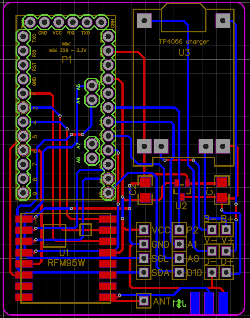
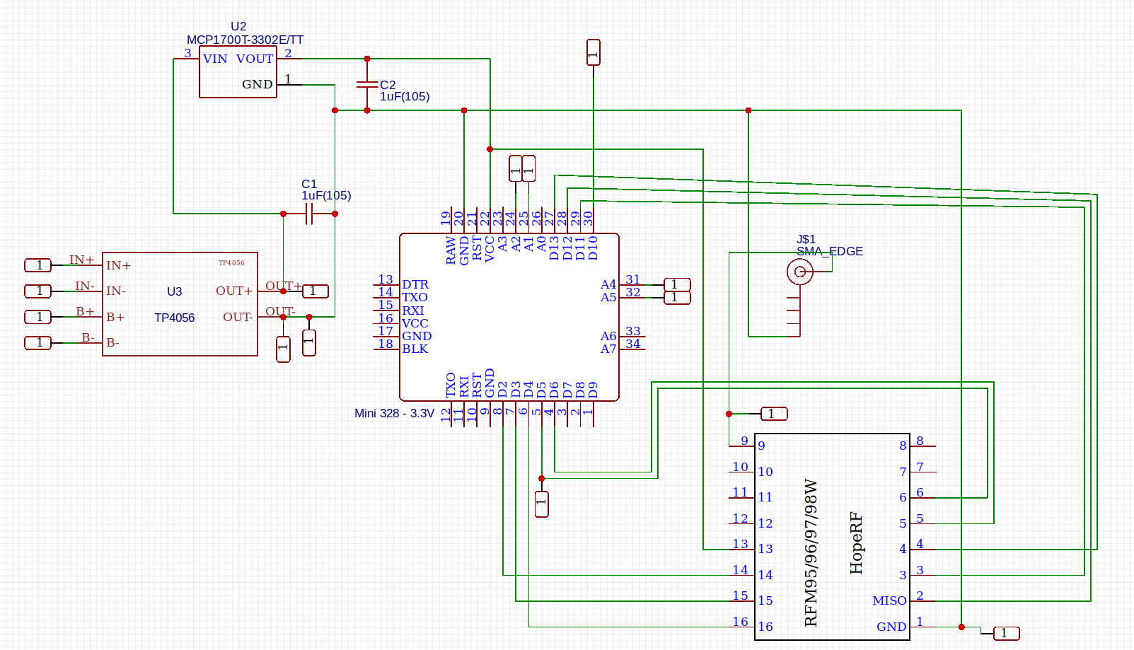
I am working on a PCB for personal projects that implements a Low Power Lora node. This is what I currently have:
For the LDO I chose the MCP1700-330 since it has very low quiescent current at a decent price.
The whole thing has support for a solar panel and a LiPo Battery, so it should work for basically ever on solar.
Please remember that this is one of my first PCBs so I know it looks messy.
Do you see anything that is completely wrong or off with it? I would really like some Feedback.
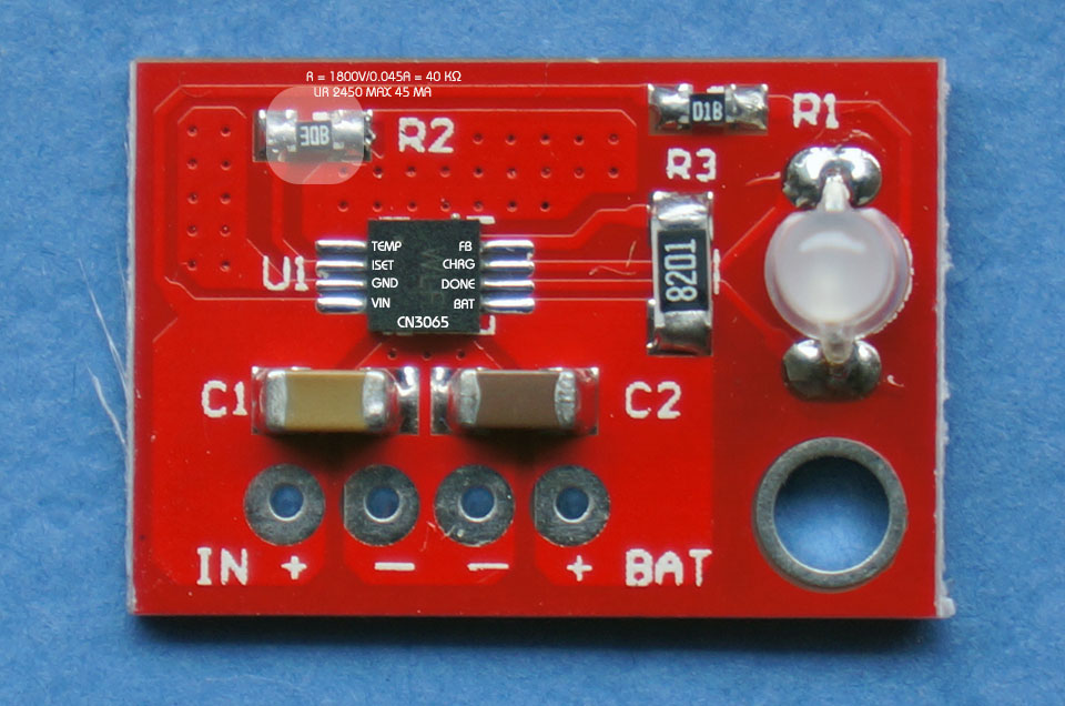
@LoRaTracker suggests limiting discharge at around 3.0V (I’ve hear 2.8V before now also) - the board you link to looks to be set at 2.5V…is that too low/acceptable?
@LoRaTracker Thanks for your input. I actually researched this and it seems 2.5V is fine. Look at this chart https://engineering.tamu.edu/media/4247819/ds-battery-panasonic-18650ncr.pdf the difference between 2.5V and 3V is 3% effectively. Also a thing to note: The way this node is set up it will be highly unlikely that the battery will every be discharged that far anyway.
I would suggest to create a ground plane, then you will need much less tracks and it is easier to route.
The MCP1700-33 is a good choice.
I do use more or less the same components (TP4056 with protection circuit), MCP1700-33, RFM95 and arduino mini pro).
So far it is working nicely, but I haven’t yet checked how well it does work with solar charging, neither how well the discharge protection is working. Keep in mind that if using the internal oscillator for low power sleep, it has to be calibrated or it will be very inaccurate.
Maybe you would like to also implement a way to monitor battery voltage. This can be done with a voltage divider connected to an analog pin.
A voltage divider for battery measurements sounds very nice. Do you happen to have the components in mind that I would need to use there? (What values for the resistors).
I have calculated the power usage for my use case and the 55mmx80mm panel that I am using should be more than enough to always power the node.
solar hours per day
real charge current
transmissions per hour
payload size
SF
sleepmode
type of connected sensor
The TP4056 is cheap, but not designed for solar charging, for that to work youll need a MPTT chip that has build in protection for overcharging and works in a cloudy environment to without damaging the lipo.
A recommended battery cut-off of 3.0V is what you will find if you Google it. The Internet can be wrong of course, but its difficult to find anyone recommending 2.4v as the cutoff.
Commercial equipment using LiPos does nopt rely on these very low cutoffs, your phone, tablet or laptop will typically shut down gracefully when the battery is low, likley between 3.3v to 3.0v. Wonder why this is ?
LiPos, when used with properly designed battery mananagement circuits, such as in phones, tablets and laptops, are safe enough and if the battery has an additional protection circuit fitted as well its a useful backstop in case the devices chargeing circuits fail, which can happen.
I also question whether LiPos are a good choice for nodes which will in general be expected to operate un-attended and un-observed for long periods. I don’t know of another battery technology that can spontaneously burst into flames some time after receiving a shock, being dropped for instance, its happened to me several times.
If hobbyists fully understand how to manage and care for LiPos and understand the risks involved then by all means use them, but it seems that all too often the prime consideration is cheapness.